How to Select a Pneumatic Cylinder for Packaging, Assembly, and Handling Equipment
Select bore, stroke, guidance, mounting, cushioning, sensing, and materials from the real machine duty instead of relying on bore and stroke alone.
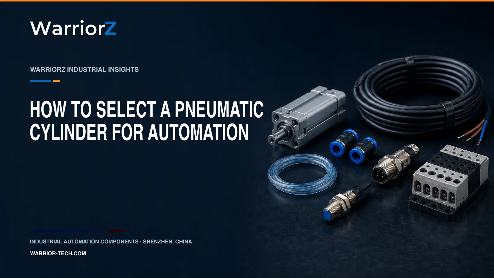
Pneumatic cylinder selection starts with the machine task, not a bore-and-stroke label. Bore provides a first check on force, but the usable result also depends on pressure at the actuator, extension or retraction area, side load, guidance, mounting, stroke time, cushioning, environment, and the required state after energy loss. Select the complete motion arrangement, then confirm the exact cylinder and accessories with the manufacturer's data sheet and sizing tool.
Factory, line, equipment, and action
Factory and line | Equipment | Typical cylinder action | Main design question |
|---|---|---|---|
Carton plant, case-packing line | Product pusher | Move a filled carton into a case | Can the mechanism supply force through the full stroke within the takt time? |
Electronics factory, assembly line | Workpiece nest | Clamp a housing for testing or screwdriving | Is the clamp force limited so the housing is not damaged? |
Automotive supplier, fixture line | Locating or clamping unit | Position a bracket before welding | How are side load, weld spatter, and loss of air handled? |
Distribution center, conveyor line | Stop gate or transfer unit | Stop and release a tote | Does the drive absorb impact, or should the mechanism use a separate stop and guide? |
Food factory, secondary-packaging line | Reject or lane-change unit | Divert sealed packs | Are washdown chemicals, corrosion, exhaust, and cleanability relevant at the installation point? |
The table is a starting map. The machine designer still needs measured or calculated load data, a motion profile, and a risk assessment.
Build a selection record before choosing a series
Record the action in plain terms: push, pull, lift, clamp, stop, index, or guide. State the moving mass, external force through the stroke, direction of gravity, acceleration target, impact, and any linkage ratio. Give the minimum pressure measured at the cylinder during the demanding part of the cycle. Idle supply pressure is not enough.
Add the full stroke, available installation envelope, required end positions, extend and retract times, cycles per minute, dwell under pressure, and expected service life. Note side force and moment at the rod connection. A piston rod should not be treated as a machine guide unless the exact product documentation allows the load. Use an external guide or guided drive where the mechanism imposes transverse force or moment.
Define mounting and alignment. A fixed mount suits an axial load only when the machine structure and load path remain aligned. Pivot mounting follows an arc but must match the mechanism geometry. Parallel rails or two synchronized cylinders can bind when tolerances are not controlled. A floating coupling or a single guided axis may be the better mechanical solution.
Finally, document ambient and media conditions: temperature at the cylinder, compressed-air quality required by the exact product, dust, chips, washdown, chemicals, corrosion, cleanroom classification, and restrictions on lubricants or paint-wetting impairment substances. Material names alone do not establish suitability.
Worked force screen for a carton pusher
This example shows the calculation boundary and does not recommend a model. A mechanism designer has established that a horizontal case-packing pusher must provide 450 N at the cylinder connection. That value already includes the measured sliding resistance, acceleration requirement, linkage geometry, and the allowance approved for this machine. The minimum pressure measured at the cylinder inlet during the push is 5 bar gauge, or 500,000 Pa above atmosphere.
For an extension screen, use A = F ÷ P. The required ideal piston area is 450 ÷ 500,000 = 0.000900 m², or 900 mm². The corresponding ideal diameter is about 33.9 mm.
A 32 mm piston has an area of about 804 mm² and a theoretical extension force of about 402 N at 5 bar gauge. It does not meet the specified 450 N even before internal friction and exhaust backpressure are considered. A 40 mm piston has an area of about 1,257 mm² and a theoretical extension force of about 628 N at the same pressure, so 40 mm becomes a candidate for the next check.
It is not yet a final selection. The sizing tool and exact data sheet must check usable force, motion time, cushioning energy, permitted load, mounting, and air consumption. If the working action is retraction, repeat the calculation with the annular area using the actual rod diameter. If the load is vertical, include gravity in the correct direction and evaluate the hazard created by pressure loss. Do not apply a universal efficiency percentage or safety factor to every machine. The project must justify its own allowances and acceptance criteria.
Force-screen input | Example value | Evidence needed on a real machine |
|---|---|---|
Required cylinder-side force | 450 N | Measurement or mechanism calculation with approved allowance |
Minimum dynamic pressure | 5 bar gauge | Pressure trace at the cylinder during simultaneous motions |
Motion direction | Extension | Confirm whether extension or annular retraction area applies |
Stroke and target time | Not used in the force screen | Required for valve, tube, cushioning, and energy checks |
Side load | Not included | Guide calculation or guided-drive data |
Choose the cylinder arrangement, not just the bore
Machine condition | Arrangement to evaluate | Verification |
|---|---|---|
Axial push or pull with controlled alignment | Piston-rod cylinder | Rod load, stroke, mounting, buckling limit, cushioning |
Side force, overhung tooling, or a moment | Guided drive or cylinder with external linear guide | Permitted forces and moments through the full stroke |
Long travel with limited installation length | Rodless drive or other linear arrangement | Guidance, sealing concept, load orientation, environmental protection |
Short stroke in a tight fixture | Compact cylinder | Mounting access, sensor space, force in both directions |
Product stopping on a live conveyor | Dedicated stopper mechanism | Permitted impact energy, conveyor speed, release sequence |
ISO 15552 establishes basic, mounting, and accessory dimensions for a defined family of cylinders with detachable mountings. Dimensional conformity can help interchangeability, but it does not prove that two products have the same seals, cushioning, sensing, force, environmental approval, or service life. Compare the complete type code and data sheet.
Speed, cushioning, and sensing
Cylinder speed is a result of the whole pneumatic chain and the moving load. Use the desired positioning time, mass, stroke, operating pressure, valve, tubing, fittings, and exhaust restrictions in a manufacturer's sizing or simulation tool. Festo's tool uses application inputs such as positioning time, mass, and stroke to propose component chains. Commissioning measurements still matter because plant pressure and installation details can differ from design inputs.
End cushioning must absorb the kinetic energy allowed by the exact cylinder documentation. A hard end impact is not solved by increasing supply pressure. Reduce speed, load, or impact, adjust the approved cushioning, or add an external shock absorber when the calculation requires it. Confirm sensor type, sensing range, cable exit, connector, and protected mounting position. Leave enough adjustment and replacement access.
Environment and cleanroom boundary
Do not translate a requirement such as stainless steel, FKM, PTFE, or cleanroom use into a generic cylinder rule. Check the exact product declaration for temperature, seal and lubricant compatibility, corrosion resistance, cleaning agents, compressed-air quality, and installation orientation. Festo notes that cleanroom suitability depends strongly on installation position and operating parameters. An advertised cleanroom class is therefore not a site validation or proof of suitability for product contact.
For food, pharmaceutical, battery, paint, or electronics work, ask which substances may reach the component and where exhaust air goes. If the actuator is near an exposed product or critical surface, the process owner must define contamination controls.
Safety and validation boundary
A double-acting pneumatic cylinder does not have a defined position merely because the air supply fails. A vertical or load-holding function needs a machine risk assessment under the applicable standards. ISO 12100 provides the general risk assessment method, while ISO 4414 covers pneumatic system safety principles. The final measure may involve a safer mechanical arrangement, guard, support, brake, clamping unit, monitored valve function, or another validated solution.
Cylinder force calculations are not safety validation. The responsible machine builder must define the safe state, failure assumptions, test procedure, and acceptance limits. Never work beneath or inside the travel of a load supported only by compressed air.
Information needed for an inquiry
Provide the existing type code and clear nameplate images if this is a replacement. For a new duty, send the factory and line, machine function, load and force calculation, motion direction, stroke, target times, minimum dynamic pressure, tube details, mounting, guidance, side forces and moments, cushioning, sensors, cycle rate, environment, cleaning agents, air-quality requirement, and required state after energy loss. Include the current drawing and available installation space.
WarriorZ is an independent sourcing and model-identification support company. It is not Festo and cannot approve an application on the manufacturer's behalf. WarriorZ can help organize identification data and source an exact or reviewed alternative part. The machine designer retains responsibility for selection, safety, and validation. Review pneumatic components, Festo sourcing support, the related valve and cylinder matching guide, or use the inquiry form.
Sources and verification basis
These references support the documented facts, calculations, or engineering boundaries used in this article.
- Festo pneumatic cylinders and selection guidance
- Festo Pneumatic Sizing Tool
- ISO 15552:2018, basic and mounting dimensions for pneumatic cylinders
- ISO 4414:2010, pneumatic system safety requirements
- ISO 12100:2010, machinery risk assessment and risk reduction
- Festo cleanroom product qualification guidance