M8 vs M12 Sensor Cables: Coding, Pins, Material, and Motion
A practical method for matching M8 or M12 sensor cables by coding, pin assignment, electrical function, jacket, shielding, motion duty, and environment.
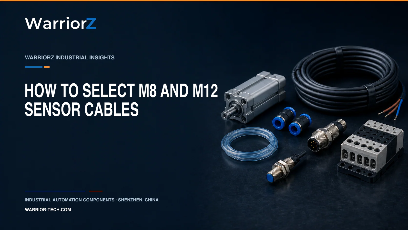
M8 and M12 identify connector families, not complete electrical compatibility. A replacement cable must also match the coding, number of contacts, pin assignment, plug or socket end, signal or power function, rated electrical values, shielding, cable construction, and motion duty. The device manual and the cable data sheet remain the final references. A connector that fits mechanically can still put supply voltage on a signal input or leave a protective function unconnected.
This distinction matters on packaging, assembly, machine-tool, intralogistics, and inspection equipment. M8 often appears where space is limited, while M12 covers a broad range of signal, data, and power interfaces. Size alone does not decide which one a machine needs. IEC 61076-2-101 and IEC 61076-2-104 define interface families and codings, but the installed device documentation determines the actual circuit.
Where M8 and M12 cables are used
Factory and line | Equipment | Connected device | What must be confirmed |
|---|---|---|---|
Food, beverage, or household-goods packaging | Labeler, cartoner, filler, or case packer | Photoelectric sensor, proximity sensor, valve island, or encoder | Pin assignment, washdown exposure, fixed or moving route, and connector orientation |
Electronics and small-parts assembly | Indexing table, screwdriving cell, test fixture, or compact robot cell | Cylinder sensor, part-present sensor, gripper, or remote I/O | Available space, I/O type, bend radius, shielding, and mating cycles |
Automotive component production | Conveyor, welding fixture, leak tester, or transfer line | Position switch, pressure sensor, identification device, or actuator | Oil and welding environment, electrical load, shield connection, and machine grounding concept |
Warehouse and intralogistics | Sorter, lift, shuttle, or pallet conveyor | Light sensor, motor module, distributed I/O, or safety-related device | Signal or power purpose, vibration, cable travel, and exact equipment schematic |
The table identifies questions, not universal connector assignments. A four-contact M12 on a sensor and a four-contact M12 on a data link may use different coding and wiring. Never transfer a pinout from a similar-looking machine.
Identify the complete interface before choosing a cable
Start at both ends of the installed cable. Record the manufacturer and complete part number of the device, the markings on the cable, the connector diameter, coding, contact count, plug or socket form, straight or angled body, locking method, and cable length. Photograph the keyway and contact face without forcing or probing the contacts. A worn label is not evidence that two assemblies are equivalent.
Identity field | Evidence to collect | Why it changes the answer |
|---|---|---|
M8 or M12 family | Thread or coupling dimensions and the exact product drawing | The outside appearance can be misleading when an adapter or molded shell covers the coupling |
Coding and key position | Device drawing, cable data sheet, and clear contact-face photograph | Coding is intended to prevent mating between interfaces assigned to different functions |
Contact count and numbering | Numbered drawing for the exact mating side | Looking into a plug and looking into a socket can mirror the apparent pattern |
Plug, socket, and body angle | Both cable-end descriptions | The electrical match can still fail mechanically in a narrow sensor bracket or cable tray |
Locking and sealing parts | Manufacturer assembly instructions | A damaged seal, incorrect coupling, or loose connection can defeat the stated protection of the assembled interface |
For a new design, choose the interface after the I/O and power architecture is defined. For maintenance, reproduce the documented interface unless an approved engineering change updates the drawing, bill of materials, and validation record.
Verify the pin assignment and electrical function
Do not use wire color as the only pinout evidence. Check the sensor or actuator manual, I/O module channel type, machine schematic, and cable drawing. Record the supply voltage range, maximum load or current, PNP or NPN logic where relevant, analog or digital signal type, normally open or normally closed behavior, data protocol, and shield termination. If a device has a configurable output, also record its parameter file or current configuration.
A useful pinout check has six lines: device pin number, device function, cable conductor, connector pin at the other end, receiving terminal or I/O channel, and schematic reference. A qualified technician can perform continuity and insulation checks only after the circuit is isolated and the connected electronics are protected from the test method. Never apply a meter or test voltage to a live safety, network, or analog circuit without the equipment procedure.
The cable's rated voltage, current, conductor cross-section, and temperature range must cover the documented circuit and installation conditions. For data or low-level analog signals, confirm the required pair construction and shielding from the protocol and device documentation. A shielded cable does not help if the shield is terminated contrary to the machine's grounding and electromagnetic-compatibility design.
Match the jacket and motion duty
Cable material is an application decision, not a quality ranking. Murrelektronik lists PVC, TPE, PUR, FEP, and FRNC cable families with different intended environments. The exact assembly data sheet must confirm chemical resistance, temperature, flame behavior, approvals, and mechanical duty. General material descriptions cannot be used as a certificate for a specific order number.
Installation | Evidence needed from the exact cable | Common error |
|---|---|---|
Fixed machine frame or cabinet | Permitted fixed bend radius, temperature, jacket compatibility, and routing method | Selecting a dynamic cable without checking whether its jacket suits the chemicals or local rules |
Repeating flex in a cable carrier | Dynamic bend radius, travel, speed, acceleration, cycle test, and installation instructions | Treating any flexible cable as a cable-carrier cable |
Robot wrist or rotating fixture | Torsion rating, bend and torsion combination, strain relief, and permitted travel | Using a cable-carrier rating as proof of torsional suitability |
Washdown or chemical exposure | Exact resistance table, connector material, sealing instructions, and cleaning process | Assuming PUR or an IP code covers every detergent, concentration, and temperature |
Leave enough length for routing and service, but do not store a moving cable as tight coils inside a carrier. Follow the specified minimum bend radius, keep the cable free of twist during installation, separate it from sharp edges and hot surfaces, and provide strain relief where the manufacturer requires it.
Treat ingress protection as an assembled condition
An IP code describes tested protection conditions under IEC 60529, but it does not make every M8 or M12 connection suitable for every plant. The stated rating may depend on correct mating, seals, tightening method, connector condition, cable entry, and unused-port caps. It does not by itself establish resistance to oil, cleaning chemicals, ultraviolet exposure, corrosion, or high-pressure cleaning.
Inspect the device receptacle as well as the cable. Bent contacts, damaged threads, contamination, missing seals, or a cracked molded body can make a new cable look faulty. De-energize the circuit according to the machine procedure, clean only with approved methods, align the coding without force, and tighten according to the manufacturer's instructions. Do not use pliers as a substitute for a specified assembly tool.
Commission the replacement without creating a second fault
Before removal, label both ends and save photographs that show routing and connector orientation. Compare the new part number and drawings with the approved bill of materials. After installation, verify strain relief, clearance from motion, unused-port protection, and cable identification. Restore power under the machine commissioning procedure, then check the raw input or output state, the machine sequence, alarms, and behavior through the full expected motion.
If the cable belongs to a safety-related control function, the replacement and test belong inside that function's change-control and validation process. A continuity check alone does not validate the safety function.
Information to send with an RFQ
Send the existing cable part number, device manufacturer and complete model, clear photographs of both ends and keyways, M8 or M12 size, coding, contact count, plug or socket form, straight or angled exit, length, conductor and shield requirements, signal or power purpose, voltage and load, fixed-flex or torsion duty, bend radius and travel, temperature, oil or chemical exposure, washdown process, and required market approvals. Include the machine schematic page when sharing it is permitted.
WarriorZ can help identify and source a cable from this evidence. WarriorZ is an independent supplier and does not claim to be Murrelektronik or an official or authorized representative. The manufacturer drawing, current data sheet, device manual, and machine documentation control the final selection.
Related WarriorZ resources
Use these pages to continue the model, component, or machine-level check:
Sources and verification basis
These references support the documented facts, calculations, or engineering boundaries used in this article.
- IEC 61076-2-101:2024, detail specification for M12 connectors with screw-locking
- IEC 61076-2-104:2026, detail specification for M8 connectors with screw-locking or snap-locking
- IEC 60529 consolidated version, Degrees of protection provided by enclosures
- Murrelektronik: Cable types for every application