High-Pressure Pneumatic Architecture for PET Stretch Blow Molding
A practical guide to pre-blow, main-blow, and exhaust valve blocks, covering pressure boundaries, air quality, cavity response, stored energy, and fault trials.
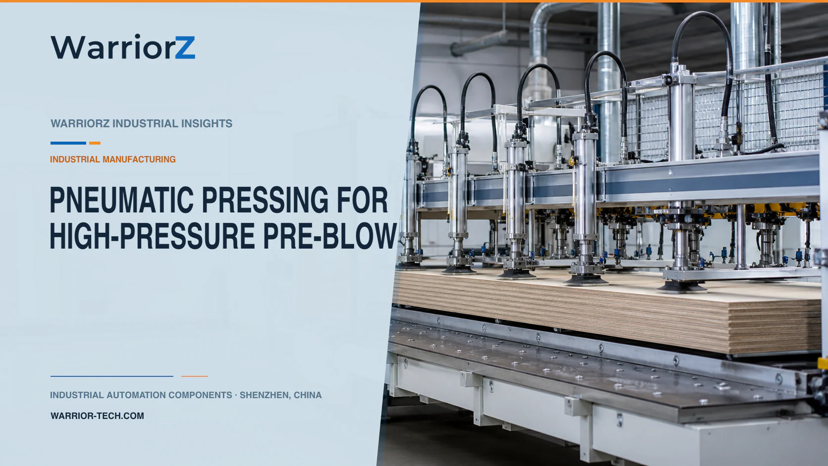
A PET stretch blow molding machine coordinates preform heating, mold closing, stretch-rod motion, pre-blow, main blow, and exhaust. The high-pressure pneumatic block must deliver the required pressure and flow at the right cavity state, then release the bottle without leaving hazardous residual pressure. A fast valve alone cannot correct excessive dead volume, poor air preparation, an undersized supply, or unstable exhaust back pressure.
WarriorZ helps factories and equipment builders identify and source pneumatic components from model numbers, photographs, drawings, and BOMs. The machine manufacturer must define pressure ratings, circuit architecture, bottle process windows, applicable laws, and validation for the destination market.
Define each blow stage at the cavity
The application is a PET stretch blow molding equipment manufacturer designing a linear or rotary machine. A dedicated high-pressure valve block controls gas delivery and exhaust for each station. The pneumatic sequence is coordinated with the preform, mold, stretch rod, and bottle transfer.
Write the required state at the blow nozzle or cavity, not only at the upstream supply header. For each recipe, define permitted pressure and timing windows, flow demand, bottle volume, preform condition, mold state, and exhaust requirement. The values must come from process development and approved component limits.
Process stage | Pneumatic objective | Evidence to retain |
|---|---|---|
Mold and nozzle ready | Establish a sealed and correctly positioned flow path | Mold, nozzle, and preform states |
Pre-blow | Apply the qualified initial pressure profile | Local pressure response and command timing |
Stretch coordination | Keep gas delivery synchronized with mechanical motion | Stretch position and pneumatic trace |
Main blow | Deliver the required pressure and flow for final forming | Cavity response and supply behavior |
Hold or stabilization | Maintain the recipe condition as defined | Pressure stability and duration |
Exhaust | Reduce pressure through the qualified path | Residual pressure and exhaust completion |
Bottle release | Confirm nozzle and mold can move safely | Pressure-safe state and mechanical clearance |
Design the block as a pressure system
Rate every wetted and pressure-containing item for the machine's maximum credible pressure, temperature, medium, cycles, and fault conditions. This includes the manifold body, cartridges, valves, fittings, tubing, regulators, filters, sensors, seals, silencers, reservoirs, and test ports. Do not mix ordinary factory-air hardware into a high-pressure section because the connection appears to fit.
Festo's official article From the blank to the bottle under high pressure describes high-pressure valve blocks, air preparation, regulators, filters, switch-on and switch-off valves, proportional valves, and component qualification for PET stretch blow molding. Use current technical documentation for the exact products selected; a press article is not a design approval.
Keep high-pressure volume as small as the qualified architecture permits while preserving flow and serviceability. Valve placement, passage geometry, nozzle volume, and connection length influence response and air consumption. Model the circuit, then confirm it on an instrumented station.
Separate pressure levels and prevent unintended flow paths
Pre-blow and main-blow circuits may use different controlled pressure sources or paths. Define which valve can connect each source to the cavity and how backflow is prevented. Analyze single faults that could connect a higher-pressure source to a lower-rated section.
Design record | Question it must answer | Commissioning check |
|---|---|---|
Pressure-boundary map | Which components see each maximum condition? | Trace every path and isolation point |
Valve state table | What flow path exists for every command combination? | Test normal and credible fault states |
Supply model | Can header pressure and flow support simultaneous demand? | Record worst-case machine operation |
Sensor layout | Does measurement represent the cavity event? | Compare local and upstream response |
Exhaust model | Where do gas, noise, and back pressure go? | Measure residual pressure and sound controls |
Isolation plan | How is stored pressure verified and released? | Perform the maintenance procedure |
Use interlocks so blow pressure cannot be admitted without the required mold, nozzle, and machine states. Prevent an exhaust valve fault from creating an unintended pressure path to another station. If energy recovery is considered, treat its receiver, back pressure, contamination, and control effects as part of the validated system.
Control air quality and supply stability
Specify particle, water, oil, and dew-point requirements from the valve-block manufacturer, bottle process, plant conditions, and applicable product requirements. High-pressure compression can expose weaknesses in upstream air treatment. Install monitoring and service points where a degradation can be detected before it affects every station.
Pressure at the compressor or main receiver does not prove stable delivery at a rotating or fast-cycling block. Account for simultaneous station demand, distribution loss, regulator capacity, filter loading, and temperature. Trend supply pressure and local cavity response separately.
Maintenance must preserve cleanliness. Cap open lines, control tools and lubricants, and follow component instructions. A small particle can cause leakage or slow response. After service, use the approved leak, function, and pressure tests before production.
Validate timing with pressure response, not commands alone
The controller may switch valves on a precise schedule, but the gas response depends on supply, flow coefficient, dead volume, bottle volume, valve dynamics, exhaust pressure, and temperature. Record the pressure trace at a measurement point shown to represent the cavity process.
Build an acceptance envelope from qualified bottles and known process limits. Relate the trace to bottle dimensions, material distribution, visual defects, leak performance, and other product tests. A normal valve command sequence does not prove a good bottle, and one upstream pressure value cannot identify every cavity fault.
Trend valve response by station. A slow shift can indicate leakage, contamination, coil or pilot issues, filter restriction, or exhaust back pressure. Preserve station identity so maintenance does not average away a single bad cavity.
Control exhaust noise and stored high pressure
ISO 4414:2010 provides general rules and safety requirements for pneumatic systems. Apply it with the applicable high-pressure, pressure-equipment, electrical, machine, and market requirements selected by competent engineers.
For equipment placed on the relevant EU market, the European Commission's official Pressure Equipment Directive overview explains the scope and conformity framework of Directive 2014/68/EU. Applicability and classification must be determined for the actual equipment; do not infer compliance from a component pressure rating.
Route exhaust to manage noise, gas velocity, debris, condensation, and back pressure. A silencer or recovery system changes flow and timing and must be validated. Provide isolation, pressure indication, controlled discharge, and verification at the service location before opening any pressure boundary.
Validate all stations and credible faults
Run every approved preform, bottle, mold, station speed, and pressure recipe across normal supply and environmental ranges. Measure supply behavior, local pressure profiles, valve timing, leakage, exhaust completion, bottle results, and air consumption.
Challenge a leaking seal, blocked filter, restricted exhaust, failed sensor, slow valve, stuck valve, wrong recipe, missing preform, nozzle misalignment, low supply, station-to-station imbalance, power interruption, and emergency stop. Verify that pressure is contained or discharged according to the risk assessment and that recovery does not reopen a charged section.
For the downstream web-handling distinction between pneumatic contact and actual process feedback, see pneumatic nip pressure and web tension control. To review rated valves, regulators, sensors, and air preparation from an approved pressure-boundary map, send a WarriorZ PET blow-molding inquiry.
Official sources
Sources and verification basis
These references support the documented facts, calculations, or engineering boundaries used in this article.