Coordinating Pneumatic Heat-Seal Pressure, Temperature, and Time
A practical guide to building bag-machine seal windows, translating cylinder pressure into bar load, verifying seal output, and controlling heat and motion faults.
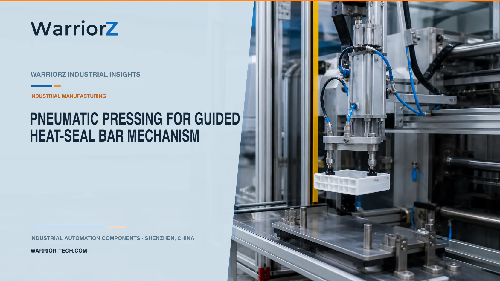
A plastic bag line positions one or more film layers, lowers a heated sealing bar, holds contact, and retracts before the next index. Pneumatics can provide fast approach and repeatable loading, but seal quality comes from the combined temperature, interface pressure, dwell time, cooling condition, film construction, and jaw geometry. Raising cylinder pressure cannot compensate reliably for an incorrect temperature or contaminated seal area.
WarriorZ provides application-oriented product information and component sourcing support for pneumatic systems. The bag producer, material supplier, and machine builder must approve the seal window, bar construction, test methods, and safety controls.
Define the film and required seal result
The application is a plastic bag manufacturing plant with unwinding, printing or registration, indexing, heat sealing, and cutting. A guided pneumatic axis lowers the heat-seal bar after the film reaches position. A regulator or proportional pressure valve sets the loading condition, and sensors confirm bar and machine states.
Create a recipe matrix for film structure, sealant layer, total thickness, number of layers, coatings or inks near the seal, bag width, seal pattern, line speed, and required product performance. Define what a good seal means: strength, continuity, peel behavior, appearance, leak performance, opening function, or another controlled requirement.
Input or setting | What it changes | Evidence needed |
|---|---|---|
Bar temperature | Heat available at the jaw | Calibrated temperature and distribution check |
Dwell time | Heat-transfer duration and production rate | Actual contact timing at line speed |
Interface pressure | Film contact and seal formation | Qualified load and bar-area calculation |
Film construction | Heat transfer and sealant response | Material identity and incoming specification |
Bar parallelism | Pressure distribution across the web | Mechanical measurement and seal map |
Release and cooling | Hot-seal disturbance and sticking | Product trials at actual index timing |
Build a production heat-seal window
ASTM's official F2029-16(2021) page describes laboratory preparation of heat seals and notes that film construction and thickness affect sealing. It also warns that laboratory and production equipment can differ, so laboratory heat-seal curves are a starting point rather than direct production recipes.
Run a designed production study over approved temperature, load, dwell, and cooling ranges. Use material-lot and thickness variation. Record actual bar temperature, contact time, pressure or force evidence, line speed, ambient condition where relevant, and the product result.
Do not adjust all variables at once during troubleshooting. If pressure is increased while temperature drifts and dwell changes with line speed, the process history becomes impossible to interpret. Protect released recipes and document who can change them.
Convert pneumatic pressure into uniform bar load
Cylinder pressure produces theoretical actuator force from effective area, but seal friction, linkage ratio, guide friction, back pressure, bar mass, and alignment determine force at the film. Divide qualified force by the actual contact area only when the load distribution justifies that calculation.
Use guided motion or external guides to keep the bar parallel. A long bar may deflect between actuators. Two cylinders on a common regulator can load unevenly because of friction or structure. Measure parallelism cold and at operating temperature, since thermal expansion can change the relationship.
A compliant backing can accommodate controlled variation, but it wears and can retain contamination. Define thickness, hardness, temperature resistance, compression set, and replacement criteria. Do not use soft backing to hide a warped bar or weak frame.
Sequence registration, contact, hold, and release
Confirm the correct recipe, film presence, registration, web stop or synchronized state, temperature readiness, and clear tool path before lowering the bar. Use a fast approach only outside the sensitive contact zone. Apply the qualified load for the actual dwell, then retract cleanly before the next index.
Sequence state | Required confirmation | Fault response |
|---|---|---|
Film indexed | Registration and web state valid | Keep bar raised |
Temperature ready | All required zones inside the released window | Inhibit sealing |
Bar approaches | Guarding and tool path valid | Stop before contact |
Contact begins | Position and pressure behavior plausible | Reject abnormal cycle |
Dwell active | Actual timing and load remain qualified | Preserve trace and stop as defined |
Bar retracts | Film releases and full clearance is reached | Prevent web index |
Seal evaluated | Required process and sampling checks pass | Route product to controlled disposition |
A timer command does not prove physical contact duration if the bar moves slowly or sticks. Use position and pressure response to establish the real event where quality risk justifies it. Detect film sticking before the web indexes and tears or wraps around the bar.
Verify seal output instead of relying on machine settings
ASTM's official F88/F88M-23 page describes seal-strength measurement for flexible barrier materials and its role in process validation, capability, and control. It also explains that test setup and material behavior influence measured results. Select applicable methods and specifications with packaging experts.
Seal strength alone may not cover continuity, leak integrity, hot tack, visual defects, or opening performance. Use the product's approved quality plan. Map results across the bar width to reveal hot or low-pressure zones. Keep sample orientation, conditioning, width, and test setup consistent.
Correlate failures with temperature-zone data, actual dwell, regulator response, bar position, material lot, and maintenance state. A machine cycle-complete bit is not a seal-quality result.
Control heat, pinch points, and sticking
ISO 4414:2010 covers pneumatic-system safety. Apply it with the machine risk assessment to crushing at the bar, hot surfaces, unexpected descent, stored air, web motion, cutter motion, and access for cleaning.
Determine the bar state after air or power loss. Gravity can lower a vertical assembly after pressure decays, while trapped air can keep force in the mechanism. Provide supports, counterbalance, controlled exhaust, guarding, and isolation as required. Before cleaning a bar, control both heat and motion energy.
Film, coating, or molten residue can stick to the bar and create a repeating defect. Use approved release surfaces and cleaning methods. Abrasive cleaning can damage coatings and alter heat transfer. Define when a contaminated or damaged cover must be replaced.
Validate materials, starts, and credible faults
Test every approved film structure, thickness, color or print condition, bag width, seal pattern, line speed, and material supplier. Include cold start, hot restart, steady production, minimum approved air supply, bar and backing wear at service limits, and production temperature variation.
Challenge a failed heater zone, temperature-sensor offset, film fold, contamination, missing layer, low pressure, regulator fault, slow cylinder, bar misalignment, sticking film, web-registration error, and interrupted dwell. Define how potentially affected product is contained and traced.
For the upstream winding distinction between pneumatic contact and process feedback, see pneumatic nip pressure and film tension control. To review guided cylinders, pressure control, valves, and sensing against a released seal study, send a WarriorZ bag-sealing inquiry.
Official sources
Sources and verification basis
These references support the documented facts, calculations, or engineering boundaries used in this article.