Low-Pressure Beams for Foam Board Cutting
Learn how to spread beam load, qualify the hold-down pressure window, coordinate cutting and push-out, and address foam dust and static risks.
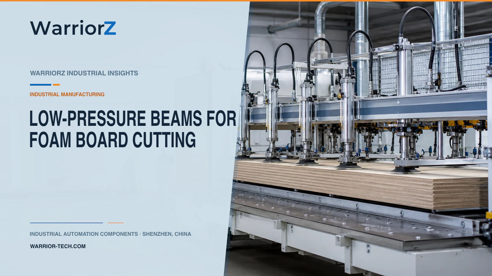
A foam board cutting line handles light material that can dent under a narrow contact strip and shift under airflow or blade reaction. A pressure beam should hold the sheet flat with the least qualified pressure, then release it without dragging the cut surface. Separate cylinders may push completed boards toward a stacker or conveyor.
WarriorZ provides BOM review, product matching, and sourcing support for documented pneumatic applications. The machine OEM owns mechanical design, controls, safeguards, and component sizing. The factory owns material classification, cutting recipes, dust and static controls, product acceptance, and safe operating procedures.
Separate hold-down and push-out duties
The pressure beam stabilizes the board during positioning and cutting. The push-out axis moves a finished part after the cutting tool reaches a safe position. Combining both tasks in one mechanism can rub the board, damage edges, or create a jam when a cut piece shifts.
Define the hold-down objective in measurable terms: no sheet lift, no position loss beyond the cut tolerance, no permanent indentation, and no unacceptable surface transfer from the pad. Define push-out by part support, travel, acceleration, receiving-conveyor state, and the maximum allowed edge load.
Machine function | Required input | Proof before motion | Common failure |
|---|---|---|---|
Board infeed | Size, thickness, and recipe | Presence and position valid | Skewed or doubled sheet |
Beam lowering | Tool clear and support ready | Correct recipe and safe cutting state | Wrong pressure recipe |
Cutting | Beam at qualified condition | Hold signal and guard state valid | Lift, slip, or dust buildup |
Beam release | Cutter parked | Cut complete and no trapped piece | Surface drag or spring release |
Push-out | Receiver available | Beam clear and part detected | Edge crushing or stack collision |
Spread contact over the board surface
Use a stiff beam so its structure does not bow between actuators. Fit a clean, replaceable contact layer selected for the foam chemistry, surface finish, temperature, and marking requirement. A soft pad can distribute load, but excessive compliance may allow local lifting or collect abrasive dust.
Multi-point cylinders should close against a mechanically aligned beam or individual floating pads that share load by design. Do not assume equal pressure produces equal contact. Cylinder friction, mounting tolerance, pad compression, beam deflection, and local board thickness can load one point first.
Keep the beam outside the cutter path and provide extraction access. If the process needs narrow fingers between cuts, validate each contact footprint because a narrow finger raises local pressure even when the pneumatic setpoint stays unchanged.
Build a material-specific pressure window
Start trials at a low command and increase only until the board stays positioned under the worst qualified cutting reaction. Then determine the upper limit from indentation, thickness recovery, coating damage, surface gloss, and any downstream lamination or bonding requirement. Repeat the test after the longest expected dwell because time under load can matter for cellular materials.
Festo's VPPM proportional-pressure regulator data provides product-specific ranges, flow, accuracy, hysteresis, electrical interfaces, and environmental conditions. Use those data only after calculating the chamber volume, required response, inlet condition, exhaust behavior, and needed pressure range. A proportional regulator is a pressure-control component, not an indentation detector.
Validation variable | Low extreme | High extreme | Record |
|---|---|---|---|
Board thickness | Thinnest approved sheet | Thickest approved sheet | Beam travel and contact pattern |
Density and stiffness | Softest approved lot | Stiffest approved lot | Hold result and indentation |
Surface condition | Clean and low friction | Dusty or coated sample | Slip and marking |
Cutter reaction | New tool condition | Qualified end-of-life tool | Part movement and cut quality |
Dwell | Normal cycle | Longest credible process stop | Recovery after release |
Supply condition | Lowest approved inlet | Highest approved inlet | Actual pressure response |
Store an approved pressure band by material family rather than letting operators raise pressure until movement stops. Protect recipe changes with access control and record overrides. After a pad, cylinder, regulator, beam, or cutting-tool change, repeat the affected qualification.
Coordinate pressure response with the cutter
Commanding the regulator and immediately enabling the cutter ignores filling time, valve response, chamber volume, and pad compression. Confirm that pressure has entered the qualified band and that the beam position is plausible before cutting begins. Use a timeout to detect slow response, not to claim correct contact by itself.
After a cut, stop or park the tool before venting the beam. A fast exhaust can let a light board jump or let a narrow strip turn into the cutting zone. Meter release where the risk assessment permits, while ensuring that restricted exhaust cannot trap hazardous energy during isolation.
The push-out cylinder should use a broad, guided contact face. Tune its velocity under load and check the receiving path. A flow control can shape speed, but the OEM must also account for supply variation, breakaway friction, payload, and end cushioning. Do not use the board as the mechanical end stop.
Treat dust and static as process hazards
Foam cutting can generate fragments or fine dust, depending on the material and method. OSHA's hazard communication guidance for combustible dusts identifies plastic dust as a category that can require an explosibility evaluation and discusses static accumulation. The factory must test or otherwise determine the properties of its actual material. A generic foam label cannot establish whether a combustible dust hazard exists.
If the assessment identifies a hazard, the factory and OEM must design collection, electrical classification, ignition control, bonding, grounding, housekeeping, and explosion protection with qualified specialists. Avoid using open compressed-air jets to disperse settled dust. Route exhaust and locate electrical or pneumatic components so they do not spread contamination into the cut zone.
Static can also disturb thin boards and dust even when no explosion hazard exists. Verify whether static control, ionization, conductive paths, or humidity controls are compatible with the product and facility. Pneumatic pressure settings do not solve electrostatic attraction.
Guard the cutter and manage stored energy
ISO 12100:2010 supplies general machinery risk-assessment and risk-reduction principles. ISO 4414:2010 covers pneumatic-system hazards through design, installation, use, and maintenance. Apply the requirements relevant to the destination market and to the real cutting technology.
Assess the cutting edge, moving beam, pusher, conveyors, stored compressed air, falling boards, dust collection, and access during changeover. A loss of air may lower a beam, raise it, or leave it suspended depending on the circuit and load. Choose the safe state from the risk assessment and provide mechanical retention where a person could enter beneath a raised assembly.
Process pressure sensors and end-position switches are not safety devices by default. Specify safety functions and their validation separately. Isolation procedures must cover pneumatic, electrical, cutting, thermal, vacuum, and dust-collection energy as applicable.
Commission every board family and credible fault
Run the approved range of sizes, thicknesses, densities, coatings, orientations, temperatures, cutting speeds, and tool conditions. Check flatness, shift, indentation immediately after release and after the product recovery period, edge quality, push-out damage, and downstream fit.
Challenge a doubled board, warped sheet, wrong recipe, missing support, pressure sensor drift, low supply, leaking cylinder, restricted exhaust, bowed beam, damaged pad, stuck valve, pusher jam, receiver blockage, and interrupted cut. The controller should preserve the current state and require a deliberate recovery when material position is unknown.
For a related restraint design with circular geometry and wire contamination, see pneumatic clamping for braided rubber hose cutting. For a selection review based on board samples and pressure-window trials, send a WarriorZ foam-cutting inquiry.
Official sources
Sources and verification basis
These references support the documented facts, calculations, or engineering boundaries used in this article.