Pneumatic Clamping for Braided Rubber Hose Cutting
A practical guide to centering braided rubber hose, qualifying a clamp-force window, sequencing the cutter, and controlling wire and dust hazards.
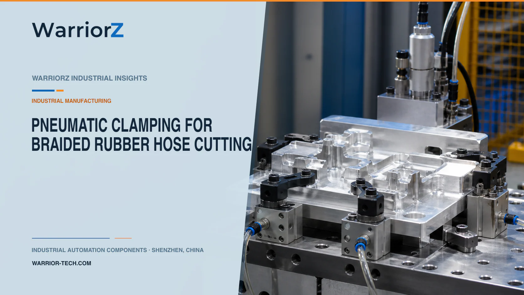
A rubber hose cutting station sits after braiding and before the next finishing or assembly step. The machine feeds a specified length, centers the hose, closes the restraint, guards the cutting zone, completes the cut, and releases the part. The restraint must stop axial movement without crushing the tube, spreading the wire braid, or leaving a permanent flat.
WarriorZ helps factories and equipment builders identify and source pneumatic components from model numbers, photographs, drawings, and BOMs. The machine OEM must design and validate the cutting station, safeguards, control system, and component selection. The factory must approve hose recipes, cut quality, exposure controls, maintenance methods, and safe work procedures.
Start with the hose construction and cut method
Do not size the clamp from outside diameter alone. Record the inner tube, reinforcement type, number and angle of braid layers, cover compound, wall thickness, cure state, allowable ovality, and cut process. A rotary blade, abrasive wheel, hot knife, and shear create different reaction forces and contamination.
The machine team should define the acceptable cut face before selecting the actuator. Useful criteria include braid displacement, loose wire length, cover tearing, tube collapse, angle error, and whether the downstream fitting process can accept the result. A repeatable clamp position cannot compensate for a worn blade or an unsuitable cut method.
Application input | Effect on the clamp | Factory evidence |
|---|---|---|
Hose diameter range | Sets jaw travel and contact geometry | Approved product drawings and samples |
Reinforcement construction | Changes radial stiffness and crush sensitivity | Sectioned hose inspection |
Cut reaction | Sets required axial restraint | Instrumented cutting trials |
Cover condition | Changes friction and marking risk | Surface acceptance standard |
Line speed and feed tolerance | Affects settling time and cut length | Production speed trials |
Dust and wire fragments | Affects seals, guides, sensors, and cleaning | Contamination assessment |
Center the hose with shaped contact surfaces
A three-point gripper can center round stock, but its standard fingers should not touch the hose unless their shape and material meet the process need. Fit replaceable shoes that wrap part of the circumference and spread load over an approved area. Remove sharp edges and gaps that can pinch the cover. For soft hose, a split collet, belt clamp, or longer saddle may distribute load better than three short pads.
Festo's official HGDD three-point gripper data shows synchronous three-jaw motion and provides force information as a function of pressure and finger lever arm. It also identifies limited suitability for grinding dust. Treat the document as product-specific engineering data, not proof that an HGDD suits rubber or wire debris. The OEM must check finger loads, custom finger mass, moment limits, contamination, sensing, and the selected fail state.
Mount the clamp close enough to the cut to resist hose movement, but leave space for the blade, chip extraction, and guard. If two restraints are needed, qualify their alignment. Opposing clamps that close on different centers can bend the hose and tilt the cut face.
Establish a clamp window instead of one pressure value
The lower boundary is the least force that prevents slip during the worst qualified cut. The upper boundary is the greatest force that does not create an unacceptable mark, ovality, braid shift, or inner-tube damage. Characterize both boundaries for every hose family. Supply pressure at a plant header does not establish contact force at the hose.
Include cylinder or gripper mechanics, shoe radius, friction, leverage, back pressure, seal friction, acceleration, and pressure variation in the calculation. Use pressure regulation only after the mechanism has been characterized. A local pressure sensor can confirm pneumatic response, while position sensing can detect closure travel. Neither signal proves that the hose was undamaged.
Check | Minimum-force trial | Maximum-force trial | Release condition |
|---|---|---|---|
Axial slip | Worst cutting reaction and lowest approved friction | Not the limiting trial | No movement beyond cut-length tolerance |
Ovality | Inspect before and after clamping | Test at the highest recipe command | Within product requirement |
Braid condition | Section representative samples | Include thin cover and soft compound | No displaced or broken reinforcement |
Surface marking | Use clean and contaminated shoes | Include longest dwell | Within visual standard |
Closure detection | Verify all hose sizes | Challenge wrong diameter and empty clamp | Fault state is unambiguous |
Interlock clamping, guarding, and cutting
Build the control as a state sequence. Confirm the fed length and correct product recipe before the clamp closes. Confirm the hose is present and the restraint reached its qualified condition before permitting the blade cycle. The movable guard must reach its safe state before hazardous cutting motion begins. After cutting, stop or park the blade before opening the guard and releasing the offcut.
A useful sequence separates hose present, clamp commanded, clamp proven, guard safe, cut active, cut complete, and release permitted. Timers may detect a failure, but elapsed time alone should not prove a safety-related state. If a pressure or position signal disagrees with the command, prevent the next hazardous action and require a defined recovery.
Keep the cut piece supported during release. A short, stiff section can spring from the clamp when stored deformation is released. Control any pneumatic ejector so it cannot launch the part or wire fragments toward an operator.
Control wire burrs, dust, and rebound
Place valves and sensors outside the direct fragment path where possible. Shield rod seals, gripper guides, tubing, and cables. Use extraction designed for the actual cutting process. Do not clean accumulations by blowing them through the machine with compressed air.
OSHA's combustible dust guidance includes plastic and rubber dust and calls for a material-specific hazard evaluation. The hazard is not established by the word rubber alone. The factory must determine whether its real dust is combustible, define collection and housekeeping controls, and address static and ignition sources. NIOSH's rubber products manufacturing review also supports a documented dust-control program for relevant exposures.
Inspect shoes for embedded wire, hardened rubber, cuts, and loss of profile. A shoe can remain mechanically intact while its contaminated surface starts marking every part. Link cleaning frequency to observed contamination and reject history rather than an arbitrary calendar interval.
Guard hazardous motion and stored air
The cutting blade, clamp, guard, feed, and ejector create separate hazards. ISO 12100:2010 provides the machinery risk-assessment framework. ISO 4414:2010 addresses pneumatic-system hazards and applies to system design, installation, operation, and maintenance. The OEM must use the standards applicable in the machine's destination market and document the risk reduction.
Define the safe response to loss of air, electrical power, a broken hose, and a jam. A spring-closing clamp may retain a part after pressure loss, but it can also preserve a pinch hazard. A spring-opening design may release stored hose energy. Select the response from the risk assessment, not from a generic preference.
Normal pressure switches and cylinder sensors do not become safety functions because the PLC reads them. Specify safeguard architecture, diagnostic coverage, reset behavior, and validation separately. Before blade changes, jam clearing, shoe replacement, or extraction service, isolate all hazardous energy and verify the isolated state.
Validate production extremes and maintain the evidence
Run each approved diameter and construction at the extremes of compound temperature, cover condition, feed speed, cut method, blade life, supply condition, and realistic contamination. Record the recipe, actual clamp response, cut result, reject reason, and tool identity. Section samples when surface inspection cannot reveal reinforcement damage.
Challenge an empty clamp, wrong hose, wrong recipe, doubled feed, sensor offset, low supply, restricted exhaust, worn shoe, embedded wire, guard fault, blade jam, and interrupted cycle. Recovery must return the machine to a known state without silently completing a cut.
For another low-marking restraint problem, see low-pressure beams for foam board cutting. For a component review based on hose samples and a defined clamp window, send a WarriorZ hose-cutting inquiry.
Official sources
Sources and verification basis
These references support the documented facts, calculations, or engineering boundaries used in this article.