Automatic Cap Closing After Injection Molding: Where Pneumatic Gripping Is Used
A practical guide to post-molding cap pickup and closing, covering hot thin walls, guided hinge presses, cavity traceability, robot handshakes, trials, and maintenance.
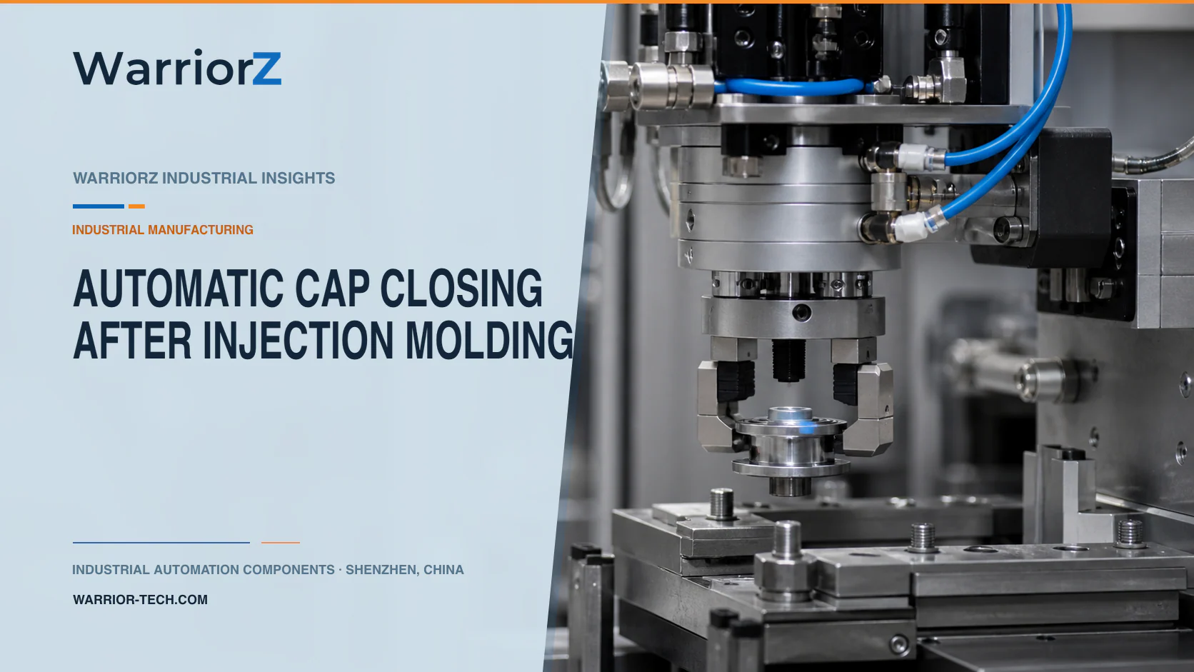
Automatic cap closing can sit immediately beside an injection molding machine, before the parts have fully cooled. A side-entry robot removes a multi-cavity set, transfers the caps into a closing station, and presents each hinge or press feature to shaped tooling. Pneumatic grippers, miniature or guided cylinders, valve terminals, and sensors can handle the short gripping and pressing actions. The difficult part is preserving thin-wall geometry, cavity identity, and mold-area safety throughout the transfer.
Define the Post-Molding Application
This application belongs in a plastic cap factory on the post-injection processing line. The equipment is a cap-closing robot and its downstream folding or press station. Its pneumatic task is to hold freshly molded caps without damaging them, operate shaped closing tools, transfer parts between verified states, and release accepted caps to the conveyor.
Festo published a cap-handling case in its official Trends in Automation page 35. The case describes a compact side-entry robot beside an injection molding machine and a cap with two opposing hinges that need closing directly after molding. Page 36 of the same case explains that the robot removes a twelve-cap molded set, closes the two hinges in successive operations, and uses Festo pneumatics to move caps between processes. Those facts describe one documented machine, not a universal cavity count or hardware recipe.
Divide the Work into Pickup, Transfer, and Closing
The EOAT should retain each cap during mold withdrawal and robot acceleration. A carrier or nest then supports the thin part while a closing tool folds a hinge, engages a snap feature, or completes another validated assembly action. Pneumatics are best assigned to short, repeatable moves whose end states can be confirmed. The electric or robotic axes usually provide the longer transfer path and programmed positioning.
Function | Typical pneumatic role | Mechanical requirement | Process evidence |
|---|---|---|---|
Mold pickup | Close gripper fingers or apply vacuum | Avoid cores, ejectors, and delicate cap walls | Every required cavity accounted for |
Transfer restraint | Hold cap in EOAT or indexed nest | Support part through robot acceleration | No shift, drop, or permanent deformation |
Hinge folding | Drive shaped press tool through short stroke | Tool follows hinge geometry without scuffing | Hinge closes and still functions as specified |
Snap or ring seating | Apply controlled pressing action if the product requires it | Support reaction force through a fixture | Feature engaged without cracking or whitening |
Discharge | Release cap to conveyor or inspection | Prevent bounce and mixed cavity order | Accepted part leaves the station and tool clears |
Grip Hot Thin-Wall Caps Without Ovalizing Them
Fresh caps can be warmer and more compliant than inspection-room samples. A jaw force that is safe after cooling may ovalize a hot skirt, mark a closure surface, or shift a hinge. Finger shape should spread load over approved features and avoid sealing surfaces or cosmetic zones. If vacuum is used, cup location and vacuum level must not dish the wall.
Festo's parallel gripper overview describes different guidance and load capabilities for mechanical grippers. That category information is only a starting point. The custom fingers, pressure, part temperature, robot acceleration, release resistance, and center-of-mass offset determine the real application load.
Qualify the tool with the hottest permitted part, the least rigid geometry, the most difficult mold release, and worn but acceptable contact elements. Inspect dimensions after cooling, not only while the gripper is holding the part.
Press the Hinge with Guided Tooling
A miniature cylinder can provide a compact stroke, but the press head should not impose lateral load or torque on an unsupported piston rod. Shaped tools often need guide rods, a slide, or another mechanical guide that carries off-axis force. Festo notes that guided cylinders combine linear motion with guidance for pressing, pushing, and related tasks.
Pneumatic pressure is an input to the actuator, not direct proof that a hinge closed correctly. Effective area, seal friction, linkage, tool alignment, part temperature, and fixture support affect the delivered load. Confirm tool position and inspect the assembled feature through an appropriate mechanical, vision, force, or functional method selected by the machine builder.
Press symptom | Possible source | Engineering check | Incorrect shortcut |
|---|---|---|---|
Hinge remains partly open | Tool path, part position, insufficient travel, or cooling state | Map tool and hinge geometry in the nest | Raise pressure without checking alignment |
Cap shows whitening or cracks | Excess local strain, sharp tool edge, or cold material | Inspect radius, support, stroke, and temperature window | Reduce dwell only |
Cap sticks to tool | Surface, heat, static, or tool contamination | Verify release geometry and cleaning | Add an uncontrolled air blast |
One cavity fails repeatedly | Mold variation, EOAT position, or nest identity | Trace the cavity through pickup and closing | Average results across all cavities |
Press reaches sensor but feature is open | Loose coupling, wrong cap position, or incomplete tool contact | Add process-result confirmation | Treat cylinder position as product proof |
Build a Traceable Sequence
The molding machine completes its validated open and ejector states. The robot enters only through the designed machine-to-robot permissions. At pickup, the EOAT grips or draws vacuum and confirms the required part states. The robot withdraws and proves clear before the molding machine receives the corresponding permission for later movement.
The robot or carrier preserves cavity identity as the caps enter the first closing station. The control confirms nest occupancy and tool-ready state, commands the pneumatic press, verifies the expected tool state, and checks the process result. A second station may close another hinge or feature. Accepted caps transfer to discharge; rejected or missing parts follow a defined route that does not silently shift cavity order.
If one pickup is missing, do not compress the remaining parts into a new anonymous sequence. Record the empty cavity position so mold maintenance and downstream quality can identify repeat patterns.
Keep Mold Interlocks Independent from Process Feedback
The robot-clear permission, mold and ejector permissions, guard system, and restart logic belong to the integrated machine safety design. A gripper-closed switch or cap-present sensor is ordinary process evidence unless incorporated into a validated safety function. The mold should never close merely because the EOAT reported a successful part pickup.
ISO 20430:2020 specifies safety requirements for injection molding machines within its scope. ISO 10218-2:2025 covers integration, commissioning, operation, and maintenance of industrial robot applications and cells. The integrator must determine the applicable standards, regional requirements, interfaces, and protective measures for the combined molding and cap-closing system.
The downstream closing tools also create pinch and crush hazards. Guard access, service modes, stored pneumatic energy, manual recovery, and reset locations need their own assessment even when the station is outside the mold envelope.
Commission Cavity by Cavity
Test every mold cavity through pickup, transfer, first close, second close where applicable, inspection, and discharge. Include the hottest and coolest approved removal conditions, minimum and maximum cycle states, maximum permitted robot acceleration, deliberate missing parts, part deformation, sensor faults, air loss, electrical restart, and tool contamination that can be introduced safely.
Measure pickup response, part shift, closing-tool motion, process result, cavity identity, reject routing, and mold-clear handshake. Preserve the qualified mold revision, EOAT revision, nest tooling, pressure and flow settings, robot program, and inspection recipe as one controlled setup. A mechanical change to a finger or press insert can invalidate more than one setting.
Control Release Air and Static
If a brief air pulse assists part release, direct it into a supported destination after the carrier is ready. Uncontrolled blow-off can flip a light cap, create noise, spread plastic dust, or break cavity order. Use the minimum validated pulse and confirm that exhaust does not affect nearby sensors or the mold area.
Static control, material condition, and cooling should be addressed at process level. Increasing blow pressure is not a reliable fix for a contaminated tool, unsuitable contact material, or excessive part temperature.
Maintain the Tooling Reference
Inspect fingers, cups if used, press inserts, guides, cylinder mounts, valve exhausts, hoses, fittings, sensors, nests, and robot dress packs. Look for plastic residue, loose couplings, polished contact faces, sensor movement, and cavity-specific wear. A guided press can still lose accuracy if its tool insert or nest loosens.
After service, run the affected cavities through the complete sequence before automatic release. The related injection-molding EOAT selection guide covers the gripper-versus-vacuum decision in more detail. Candidate families can be reviewed in the WarriorZ pneumatic component catalog.
WarriorZ helps collect documented tooling requirements and coordinate pneumatic component sourcing.
Official Technical References
Sources and verification basis
These references support the documented facts, calculations, or engineering boundaries used in this article.