Injection Molding Part Removal EOAT: How to Choose Pneumatic Grippers and Vacuum
A practical EOAT guide for hot injection-molded part removal, comparing pneumatic fingers and vacuum by geometry, deformation, cavity proof, robot motion, and mold-area safeguards.
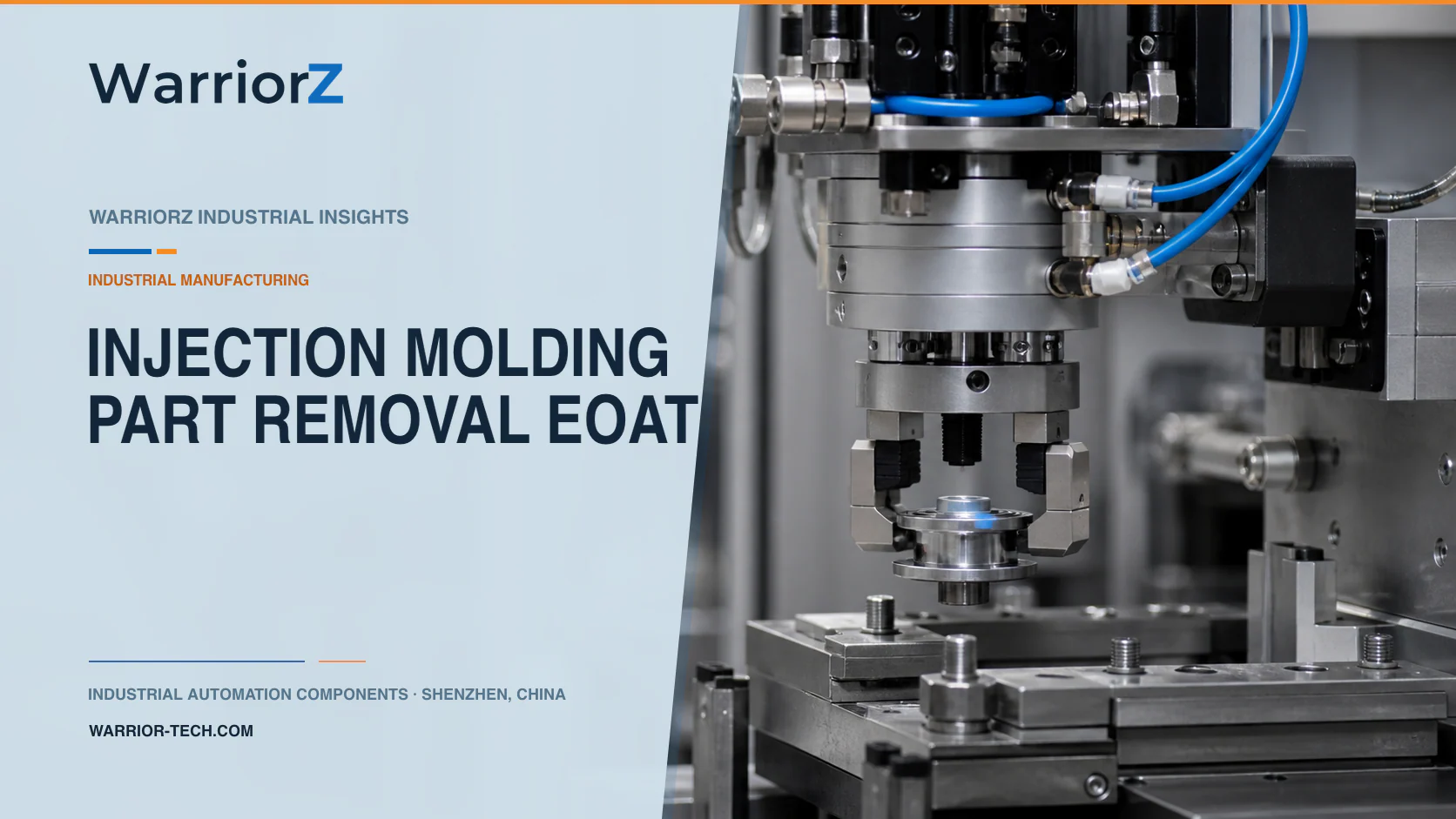
An injection-molding takeout robot has to remove hot, sometimes flexible parts without touching the mold, dropping a part into the closing area, or deforming a cosmetic surface. Pneumatic grippers and vacuum cups can both work on end-of-arm tooling, but they solve different contact problems. Selection should begin with the molded geometry, release behavior, temperature, cavity layout, allowable marks, robot acceleration, and proof-of-pick requirement.
Define the Injection-Molding Cell
This application belongs in an injection molding plant on the molding line. The equipment is the takeout robot's end-of-arm tooling, or EOAT. Its pneumatic task is to grip a sprue or molded feature with a pneumatic gripper, hold a suitable part surface with vacuum, and confirm the required pickup states before the robot exits the open mold.
Festo defines end-of-arm tooling as the gripping systems and tools mounted on a robot hand, axis, or handling system. The available technologies include mechanical grippers and vacuum cups. That broad portfolio does not determine which contact is safe for a particular molded part.
Choose Contact by Part Feature, Not Habit
A gripper needs a stable feature that tolerates jaw contact and the forces from withdrawal and robot motion. It can be useful on a sprue, tab, rib, or robust outside diameter. Vacuum needs a surface that allows a repeatable seal without cosmetic damage or unacceptable deformation. Release agent, texture, parting-line flash, holes, and curvature can make a nominally flat surface leak.
Many EOAT designs combine both methods. A gripper may control the sprue while cups stabilize multiple cavities, or separate circuits may hold parts that have different geometries. Each pickup point should have a defined job and diagnostic expectation.
Part or process feature | Gripper consideration | Vacuum consideration | Trial evidence |
|---|---|---|---|
Robust sprue or tab | Jaw geometry can create positive restraint | Seal area may be too small or irregular | No pull-off, fracture, or interference during extraction |
Broad smooth face | Jaw contact may mark an edge | Cup can spread load if surface seals | No witness mark, distortion, or leakage at hot condition |
Textured or vented surface | Feature grip may be more repeatable | Leakage may prevent reliable vacuum | Pickup response across all cavities and lots |
Soft thin wall | Grip force can crush or ovalize the part | Vacuum can dish the wall | Dimensional recovery after cooling |
Release agent or condensate | Jaw friction can change | Cup seal and material can change | Contaminated-condition test and cleaning plan |
Multi-cavity tool | Fingers must match cavity position | Branch imbalance can hide one missed part | Cavity-level part-accounting method |
Size the Mechanical Gripper as a Complete Tool
Gripper catalog force is not the force available at an arbitrary custom finger tip. Finger length, offset, friction, orientation, acceleration, part mass, withdrawal resistance, pressure, and jaw guidance affect capacity. Use the current manufacturer sizing method and observe finger-load limits. Festo's parallel gripper overview distinguishes gripper designs and guidance options for different loads and environments.
Design fingers to locate the part without wedging it more tightly as it cools. Avoid sharp edges and unsupported thin walls. Retention should not depend on an unknown coefficient of friction where a positive feature is available. Verify both a newly molded hot part and the least favorable approved process condition. A room-temperature sample on a workbench is not a sufficient extraction test.
Design Vacuum Around the Real Leakage Path
Festo states that its pneumatic vacuum generators use the Venturi principle to create vacuum from compressed air. Selection depends on cup size, leakage, hose volume, evacuation time, duty cycle, exhaust, and robot payload. A large generator cannot correct a cup placed over flash, a vent, or a surface that deforms away from the lip.
Place the generator and sensing architecture so the controller receives meaningful information before motion. One shared sensor may show an acceptable manifold condition while a branch for one cavity is open and the others seal well. Depending on the consequences, use branch isolation, additional sensing, direct part detection, or a downstream cavity-accounting check. A vacuum threshold confirms a pneumatic condition at the sensor, not the identity or quality of every molded part.
Use a Handshake-Based Removal Sequence
The injection molding machine completes the opening state and establishes the permissions defined by the cell interface. The robot confirms that its EOAT is clear and in the expected starting condition, then enters only after all required machine and cell conditions are valid. At the pickup position, the EOAT closes the selected grippers and applies vacuum. It waits for the defined gripping, vacuum, and part-presence evidence before withdrawal.
The robot exits the mold area and proves clear before the molding machine receives permission for subsequent hazardous movement. If pickup evidence is incomplete, the system follows a controlled recovery. It should not tell the press that the mold is clear when a part may remain on a core, ejector, or cavity surface.
Sequence state | Machine or robot evidence | EOAT action | Release condition |
|---|---|---|---|
Await mold | Mold and ejector states valid through the designed interface | Grippers and vacuum in start state | Entry permissions accepted |
Enter | Robot path and cell state valid | No unintended pneumatic motion | EOAT reaches pickup pose without contact |
Acquire | Robot at qualified pose | Grip and apply vacuum in defined order | Required part evidence accepted |
Withdraw | Grip states remain monitored | Maintain hold through acceleration | Robot clears mold envelope |
Handover | Destination ready | Place parts and sprue using controlled release | Part presence confirmed downstream |
Recover fault | Machine remains in the engineered protected state | Do not repeat blindly | Cause identified and safe reset completed |
Keep Process Data and Safety Signals Separate
An interface can exchange mold position, ejector state, part tracking, and robot status. Not every data channel is safety-related. The official EUROMAP 79 page states that its OPC UA interface supports machine-to-robot data and that safety signals are not exchanged through that OPC UA channel; it points to a separate electrical interface for safety signals.
The integrator must use the interface edition and safety architecture applicable to the delivered machines. A normal PLC bit called mold open or robot clear is not automatically a validated safety signal. The EOAT's ordinary gripper, vacuum, and cylinder sensors are process feedback unless the complete safety function is engineered and validated.
Address Mold-Area and Robot-Cell Hazards
ISO 20430:2020 specifies safety requirements for injection molding machines within its scope. ISO 10218-2:2025 addresses industrial robot applications and robot cells. The cell integrator must determine the applicable standards, regional regulations, interfaces, guards, access controls, reset locations, and safe modes for the combined system.
Consider a dropped hot part, a part retained in the mold, unintended ejector motion, robot entry at the wrong machine state, pneumatic energy during maintenance, and recovery after power or air loss. The correct response is a machine-level design decision. It cannot be delegated to a vacuum switch or a normally closed gripper without failure analysis.
Commission Every Cavity and Failure Case
Use actual production parts at the hottest and coolest approved removal conditions, the most difficult release state, maximum allowed robot acceleration, minimum and maximum part mass, representative release agent, worn but acceptable cups and fingers, and low permitted pneumatic supply. Confirm dimensional recovery, surface marks, sprue damage, pickup response, cavity accounting, and downstream placement.
Safely challenge a missed cup, blocked line, leak, failed gripper signal, retained part, dropped part, missing cavity, air loss, and restart. Measure the full command-to-secure interval rather than copying a valve switching time. Preserve the approved EOAT recipe, robot motion profile, and mold revision together.
Maintain EOAT Without Losing Traceability
Inspect cup lips, filters, hoses, generator exhaust, gripper guides, fingers, fasteners, sensor brackets, fittings, and robot dress packs. Release agent and plastic dust can change both friction and vacuum response. A replacement finger or cup that looks similar may change reach, compliance, material compatibility, or sensor behavior.
After service, verify every cavity and the mold-clear sequence before restoring automatic production. The related automatic cap-closing guide follows molded parts into a downstream pneumatic handling and pressing station. Candidate families can be reviewed in the WarriorZ pneumatic component catalog.
WarriorZ helps organize EOAT application data, pneumatic component comparisons, and sourcing inputs.
Official Technical References
Sources and verification basis
These references support the documented facts, calculations, or engineering boundaries used in this article.