Pneumatic Clamping for In-Line Plastic Pipe Flying Cutters
A practical guide to synchronizing a flying cutter, distributing clamp force on hot plastic pipe, protecting roundness, and recovering safely from cutting faults.
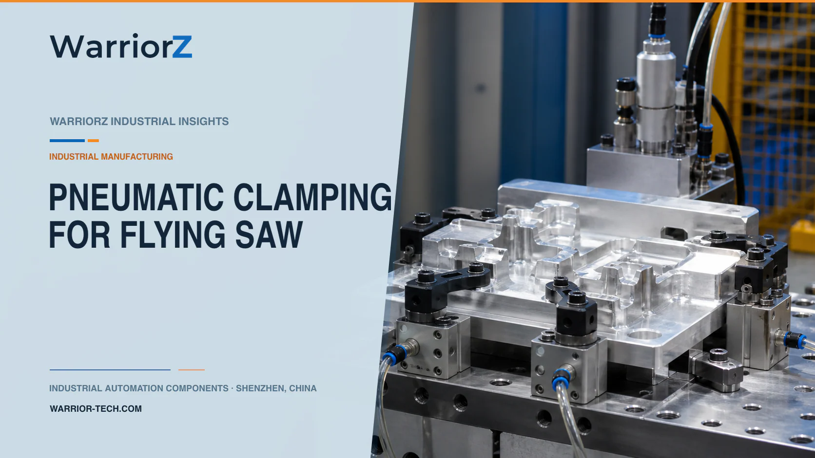
A plastic pipe extrusion line keeps moving while a flying saw or knife cuts finished lengths. The cutting carriage accelerates to match pipe speed, pneumatic jaws close around the hot profile, the cut is made, and the carriage releases and returns. If the clamp closes too early, too hard, or with poor support, it can flatten the pipe and leave a mark that remains after cooling.
WarriorZ supports maintenance and automation teams with pneumatic spare-part identification, product matching, and international supply. The pipe producer must approve dimensional limits, cut quality, clamping contact, line speed, and machine safety for each material and product.
Define the moving cut and the hot pipe state
The application is a thermoplastic pipe factory with an extrusion, cooling, haul-off, and in-line cutting process. The cutter carriage travels with the pipe during the cut. A guided clamp holds the pipe relative to the saw or knife, not necessarily against all axial line forces.
Build a product matrix for resin, outside diameter, wall thickness, temperature at cutting, ovality, surface finish, line speed, and required length tolerance. Temperature is especially important because the same jaw force can produce different deformation before and after cooling. Measure the actual pipe state at the cutter rather than relying only on the extruder setpoint.
Input condition | Likely effect at the clamp | Verification |
|---|---|---|
Higher pipe temperature | Lower local stiffness and more marking risk | Temperature and post-cooling dimensional check |
Thin wall or large diameter | Greater ovality under concentrated load | Qualified jaw length and force trial |
Wet or slippery surface | Reduced axial friction | Slip measurement during representative cutting |
Line-speed change | Different synchronization and dwell time | Carriage-speed and position trace |
Blade wear or chip loading | Higher cutting reaction | Cut-force trend and tool inspection |
Guide or jaw misalignment | Local dent and angled cut | Mechanical alignment and cut squareness check |
Spread clamping force around the pipe
Use shaped jaws or saddles that contact a broad approved arc and length. Avoid a narrow pad that creates a line load. The jaw profile should match the permitted diameter range without pinching at its edges. Replaceable liners can protect the surface, but their friction, compression, temperature resistance, contamination, and wear must be tested.
Calculate the grip needed to resist the qualified cutting reaction and carriage dynamics, then confirm it on hot product. Cylinder pressure is only one factor. Jaw linkage, seal friction, back pressure, guide friction, liner condition, and geometry determine actual contact force.
Measure ovality and surface marking after the pipe has cooled to the condition used for final inspection. A pipe that springs back immediately after release may still retain a dimensional or cosmetic defect. Do not increase pressure to compensate for a dull blade or a carriage that is not synchronized.
Synchronize the carriage before clamping
The pipe must not drag through closed jaws while the carriage is still accelerating. Use the line encoder and carriage feedback selected by the machine builder to establish the permitted speed and position difference. Close the jaws only inside that window, then confirm the expected clamping state before enabling the cut.
Sequence state | Required condition | Fault response |
|---|---|---|
Length target approaching | Valid line and carriage position signals | Do not launch the cut cycle |
Carriage accelerates | Travel path clear and recipe correct | Abort before jaw contact |
Speed matched | Difference inside the qualified window | Keep clamps open |
Pipe clamped | Jaw position and process pressure behavior valid | Inhibit saw or knife motion |
Cut completes | Tool result and carriage state accepted | Preserve clamp until risk-assessed stop |
Jaws open | Full pipe and tool clearance confirmed | Keep return and product transfer inhibited |
Carriage returns | Safe deceleration and home position | Block the next length command |
A timer cannot prove speed match. Line speed can change, an encoder can disagree, or a drive may lag. Preserve the actual speed difference, clamp transition time, and cut position for diagnostics. If the line stops during a cut, define whether the pipe remains supported, the blade retracts, and the carriage can be recovered without a second uncontrolled cut.
Guide clamp and cutter loads separately
Use guides sized for the jaw mass, stroke, offset, and side loads. The current Festo DFM guided-drive datasheet publishes product-specific load, moment, stroke, and operating information. It illustrates why a cylinder bore alone cannot define the mechanism.
The cutting head needs its own qualified guide and structural reaction path. Do not transmit blade reaction through a slender cylinder rod or soft pipe wall. Check the carriage frame, jaw carrier, cutter alignment, and bearings together. A compliant jaw can protect the product, but excessive movement can allow a skewed cut.
Locate valves to obtain repeatable response without placing them in the direct chip, water, or heat path. Tube volume and exhaust restriction affect closing and release time. If independent jaw circuits are used, detect a lagging side rather than assuming a common valve command produces equal contact.
Control chips, water, and maintenance hazards
Cooling water and chips can contaminate guides, silencers, sensors, and jaw liners. Shield components while keeping them inspectable. Route exhaust so it does not blow chips toward workers, sensors, or the pipe surface. Define cleaning methods that do not force debris into seals.
OSHA's official machine guarding guidance identifies hazards from points of operation, rotating parts, and ingoing nip points. The flying carriage adds high-speed travel and changing hazard locations. The machine risk assessment must address access to the blade, clamp pinch zones, carriage travel, ejected chips, and unexpected restart.
ISO 4414:2010 covers pneumatic-system safety requirements. Isolate and dissipate stored energy before reaching into clamps or servicing the cutter. Exhausting air does not remove carriage inertia, gravity, a loaded spring, or blade energy.
Separate process control from product acceptance
Jaw position, regulated pressure, and cylinder end signals show machine state. They do not prove final pipe geometry, length, or cut quality. Define product checks such as outside diameter, ovality, cut squareness, burr or chip condition, surface marking, and length after cooling. Use the actual product specification and qualified gauges.
Trend clamp pressure behavior, carriage synchronization, cut time, and tool condition, but do not widen product limits to keep a worn process running. A rise in cutting reaction can point to blade wear, poor alignment, resin buildup, or a support problem.
Keep rejected lengths identifiable. Automatic recutting may create an unsafe short section or hide the initial fault. Route them through a controlled disposition.
Validate speed, temperature, and credible faults
Run the full diameter, wall, resin, temperature, and line-speed range. Include the least stiff hot pipe, lowest credible friction, worn jaw liners at their service limit, minimum approved supply pressure, and representative water and chip contamination. Measure speed match, grip slip, ovality, surface marks, cut geometry, and length.
Challenge wrong recipes, cold or overheated pipe, missing product, one jaw blocked, dull blade, encoder disagreement, low pressure, restricted exhaust, sensor failure, carriage stop, and loss of power or air at every sequence stage. Define safe recovery before production release.
For the preceding tool-change safety boundary, see pneumatic quick mold change with positive retention. To review guided clamps, regulators, valves, and sensors from an approved cutter design, send a WarriorZ flying-cut inquiry.
Official sources
Sources and verification basis
These references support the documented facts, calculations, or engineering boundaries used in this article.