Pneumatic Quick Mold Change With Positive Mechanical Retention
A practical guide to separating pneumatic motion from mold retention, sequencing media couplers, confirming actual lock engagement, and recovering interrupted changes.
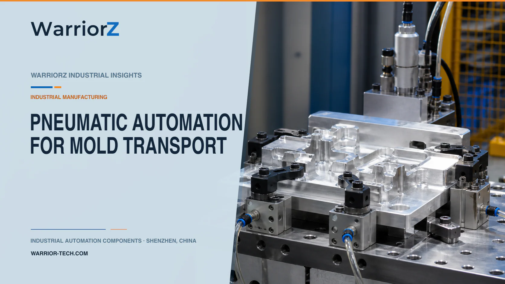
An injection molding plant can shorten changeovers by automating mold locating pins, media couplers, access doors, and auxiliary clamps. Pneumatics are useful for moving these devices, but compressed air should not be confused with positive retention of a heavy mold. The lock must remain effective in the fault conditions defined by the machine risk assessment, including loss of air, hose failure, valve faults, and interrupted changeover.
Mold mass, retention, interfaces, media conditions, safeguards, and change procedures must be approved for the actual press and tool. WarriorZ provides application-oriented product information and component sourcing support for pneumatic systems.
Separate movement, location, and retention
The application is an injection molding plant with a rapid mold-change station. A transport cart or overhead system brings the mold to the press. Locators establish its position, a qualified clamping system retains it on the platen, and automated water, air, hydraulic, or electrical connectors are engaged only after the mold is secured.
A pneumatic cylinder may push a locating pin or operate a positive mechanical latch. That does not mean air pressure is the retaining element. Define the load path after the cylinder stops moving. A shoulder, wedge, clamp, or other engineered mechanism should carry the mold load as specified by the machine and clamping-system manufacturer.
Function | Suitable pneumatic role | Evidence required before the next step |
|---|---|---|
Mold approach | Move a stop, guide, or connector | Mold supported and inside the capture zone |
Fine location | Insert a qualified locating pin | Actual mold datum reached without forcing |
Mold retention | Actuate an approved mechanical clamp | Positive engagement and required load capacity confirmed |
Media connection | Drive coupler motion | Mold locked, circuits identified, pressure safely controlled |
Guard movement | Open or close an access device | Guard state evaluated by the machine safety system |
Release | Withdraw couplers and unlock in sequence | Media isolated, mold supported, hazardous state ended |
Make the lock independent of supply pressure
Do not rely on trapped air as permanent mold retention. Air can leak through seals, fittings, valves, and damaged tubing. A check valve may slow pressure loss, but it does not turn a pressure-dependent clamp into a positive mechanical lock. If pneumatics drive a locking pin, verify the actual engaged position and design the mechanism so loss of pressure does not withdraw it unintentionally.
Two confirmations should provide meaningful information. Two switches watching the same piston magnet may share the same failure and still miss a disconnected linkage. Where the risk assessment requires stronger evidence, monitor the actual clamp or pin position, the mold position, and any required retained-force or pressure condition through appropriately independent means.
Festo's official safe pneumatics overview states that pneumatic safety functions must be evaluated at system level and remain the machine manufacturer's responsibility. Use current component safety data only within the validated circuit and control architecture.
Sequence mold support, locking, and media connection
The mold remains mechanically supported during the entire change. Confirm press state, mold identity, cart or crane capacity, and the receiving position before advancing. Locate without using excessive cylinder force to correct a misaligned transport. Engage and verify the retention system before the lifting or transport device transfers load.
Changeover state | Required confirmation | Action kept inhibited |
|---|---|---|
Old mold prepared | Process energy and media handled by the approved procedure | Clamp release |
Old mold supported | Transfer device carrying the defined load | Retention withdrawal |
New mold presented | Correct tool ID, orientation, and platen clearance | Media coupling and press motion |
Mold located | Datums reached inside tolerance | Final lock command if misaligned |
Positive lock engaged | Actual retaining elements confirmed | Transfer support removal |
Media connected | Correct circuit identity, connection, and leak check | Heating, flow, or production enable |
Change complete | Guards, recipes, and all auxiliary states accepted | Automatic press cycle |
Do not pressurize hot-water or other media circuits merely because a connector cylinder reached its end. Confirm that the correct halves are fully engaged and that the circuit is ready. A partial connection can hold briefly and then leak under temperature or pressure.
Control hot media and stored energy
Map each water, air, hydraulic, electrical, and sensor connection. Prevent cross-connection through keyed interfaces, labeling, tool identification, or another validated method. Account for residual pressure, hot liquid, thermal expansion, and gravity drainage before a coupler opens.
Place valves so isolated energy can be verified and released without exposing the worker to the connector path. A pressure sensor can help show circuit state, but sensor location matters. Pressure trapped between a closed valve and coupler may remain even when an upstream gauge reads zero.
OSHA's official control of hazardous energy regulation, 29 CFR 1910.147, applies in the United States according to its scope and exceptions. The employer must determine when servicing or maintenance requires an energy-control procedure. An automated production change sequence does not remove the need for proper isolation when a person enters or performs servicing.
Integrate with the injection molding machine
The official ISO 20430:2020 page identifies safety requirements for injection molding machines and explicitly notes that the mold itself is outside that document's scope. That boundary reinforces the need to assess the press, mold, quick-change equipment, transfer device, and connectors as an integrated system.
ISO 4414:2010 covers pneumatic-system rules and safety requirements. Apply it together with the machine-specific requirements and risk assessment. Consider crushing between mold and platen, unexpected platen movement, dropped loads, pin shear, connector release, stored media pressure, hot surfaces, and restart from an incomplete state.
Normal automation sensors are not automatically safety devices. Select architecture, diagnostic coverage, components, and validation from the required safety function. Guard-door cylinders may move the door, but the safety-related guard condition belongs to the qualified machine control system.
Design fault recovery before commissioning
Define recovery for a mold stopped between supports, a pin that enters only partly, a connector that fails to release, a pressure sensor disagreement, or loss of air during the change. Preserve tool identity and sequence state. Prevent a restart from assuming that every previous command completed.
Manual overrides should not bypass mold support, positive locking, media isolation, or guarding. Provide visible state indicators and an authorized procedure for securing the load before anyone enters. If a lock cannot be verified, keep the mold supported and the press inhibited until competent personnel resolve it.
Use mechanical service supports where required. Exhausting a cylinder does not remove gravity or stored energy in a linkage. After maintenance, verify linkage connection and actual lock movement, not only the cylinder sensor.
Validate the heaviest mold and credible failures
Test every approved mold interface, mass range, connector set, and transport method. Include the least favorable center of gravity, platen tolerance, hot and cold conditions, minimum approved supply pressure, worn locating features at their service limit, and realistic contamination.
Challenge wrong mold identity, reversed connector mapping, partial pin engagement, broken linkage, failed sensor, slow valve, leaking circuit, stuck coupler, interrupted power, lost air, and residual hot media. Measure actual lock engagement, connector travel, leak behavior, change time, and safe recovery.
For a neighboring plastics process that also separates clamping from motion synchronization, see pneumatic clamping for plastic pipe flying cutters. To review cylinders, valves, sensors, and air preparation from an approved mold-change concept, send a WarriorZ mold-change inquiry.
Official sources
Sources and verification basis
These references support the documented facts, calculations, or engineering boundaries used in this article.