Maintaining Pneumatics on Plastic Profile Vacuum Sizing Tanks
A practical guide to process-valve feedback, lid clamping, vacuum equalization, condensation control, and dimensional troubleshooting on profile sizing tanks.
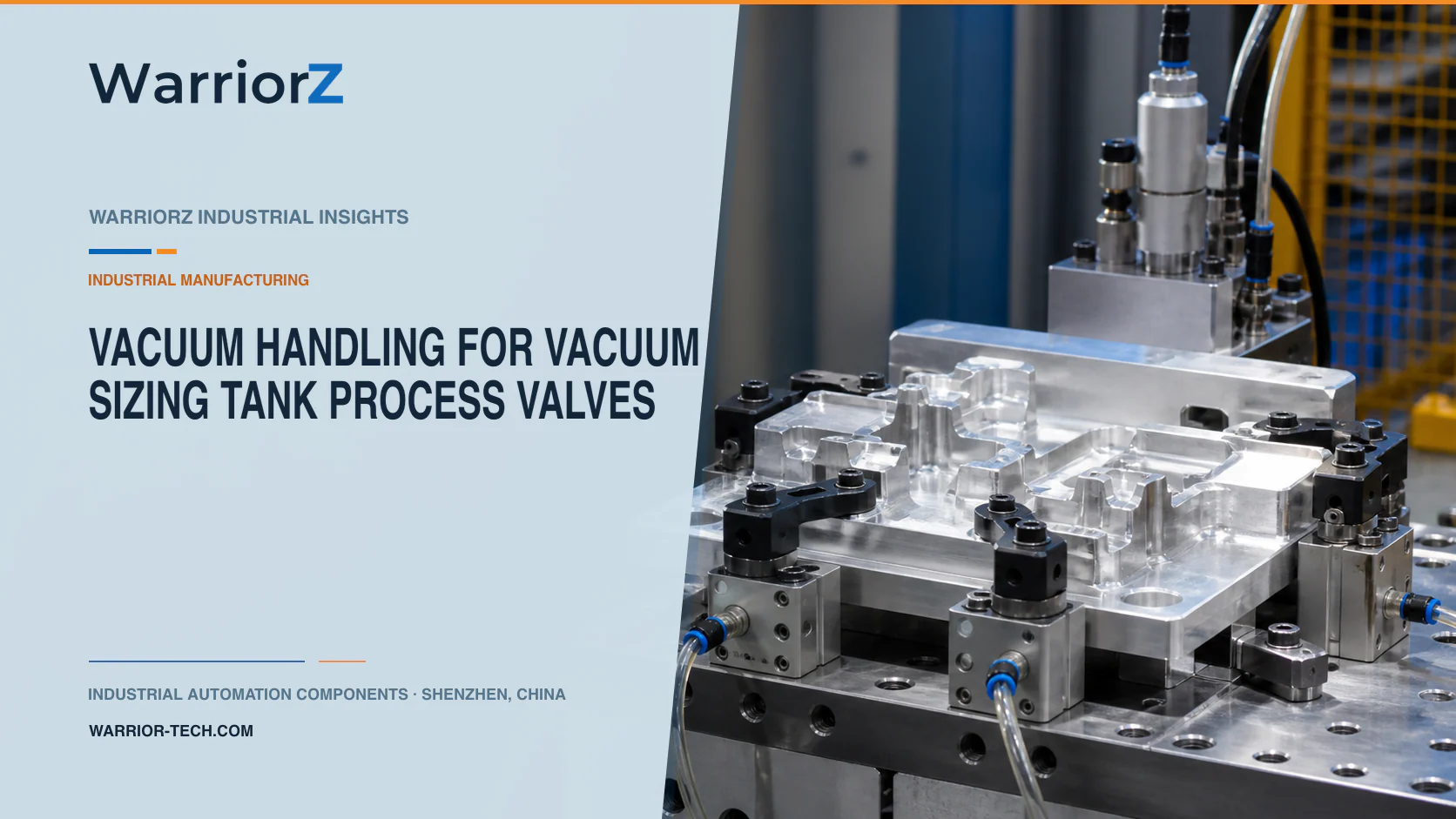
A plastic profile extrusion line uses a vacuum sizing tank to hold the hot profile against calibrator surfaces while cooling water removes heat. Pneumatically actuated process valves can route water and vacuum, and compact cylinders can clamp access lids. Condensation, scale, seal wear, and small leaks can change the process slowly enough that operators compensate with setpoints instead of finding the mechanical cause.
Valve materials, process media, vacuum limits, lid retention, dimensional recipes, and maintenance intervals must be approved for the actual line. WarriorZ supports documented pneumatic requirements with component comparison, sourcing, and delivery coordination.
Map the vacuum, water, air, and drain circuits
The application is a plastic profile factory with extrusion, calibration, cooling, haul-off, and cutting. The sizing tank contains calibrators, water sprays or baths, vacuum zones, drains, and access lids. Compressed air operates selected valves and lid clamps; it should remain clearly separated from the water and vacuum process paths.
Create a piping and instrumentation diagram that identifies every process valve, pilot valve, actuator, sensor, vent, drain, filter, and isolation point. Mark the normal and fault position of each valve. A label such as valve 4 is not enough when maintenance must distinguish vacuum isolation from cooling-water bypass.
Circuit or device | Required information | Typical hidden fault |
|---|---|---|
Vacuum supply | Zone, setpoint range, isolation, and vent path | Small leak or restricted filter |
Cooling water | Flow direction, temperature, pressure, and drain | Scale, blocked nozzle, or valve not fully open |
Pneumatic pilot air | Quality, pressure, isolation, and exhaust | Condensate, tubing leak, or slow pilot valve |
Lid clamp | Stroke, contact point, and actual locked state | Misadjusted linkage or compressed gasket |
Tank seal | Material, compression, joint, and replacement limit | Flattening, tear, debris, or chemical attack |
Instrument line | Measurement point and cleaning method | Water trap or clogged impulse path |
Select process valves for the actual media
The water or vacuum valve body sees process media; its pneumatic actuator sees pilot air. Check both sides. Valve type, body and seal materials, pressure and vacuum rating, temperature, contamination tolerance, flow capacity, and cleaning chemical compatibility must match the real service.
Festo's official process valve automation overview describes on-off and flow-control architectures, pneumatic actuators, pilot valves, positioners, and actual valve-position feedback. It is a selection framework, not an endorsement of one valve for every sizing tank.
For an on-off function, confirm full open and closed positions at the process valve, not only at the pilot solenoid. A disconnected coupling or seized stem can leave the pilot working while the media valve remains wrong. For modulating service, characterize the complete valve, actuator, positioner, and process response. Do not infer water flow from actuator position without commissioning data.
Locate pilot valves and manifolds away from direct spray and heat where possible. Route exhaust so humid air and droplets are not drawn into electrical connectors or sensor faces.
Clamp the lid without using it to hide seal damage
Use distributed clamps to compress the gasket evenly within its qualified range. The tank flange and lid should be stiff enough to maintain the seal without excessive cylinder force. A high clamp pressure can temporarily mask a damaged gasket while bending the lid or making later release hazardous.
Set mechanical stops or linkage geometry so cylinder travel does not overcompress the seal. Confirm actual clamp engagement. One cylinder end sensor may not detect a disconnected toggle or a lid held up by debris. Where several clamps are required, identify which one failed.
The lid should not open while a hazardous pressure difference remains. Provide an engineered vent or equalization path and confirm the required tank state before releasing clamps. Vacuum can hold a lid after clamps retract; positive pressure from cleaning or a blocked vent can push it outward. Recovery must address both directions.
Sequence start-up, production, and shutdown
Verify tank clean, calibrator installed, lid and gasket correct, drains ready, and clamps engaged before enabling the process recipe. Establish cooling and vacuum in the order specified by the line builder. Monitor actual conditions while the profile enters the sizing section.
Sequence state | Required evidence | Action inhibited on fault |
|---|---|---|
Tank prepared | Correct tooling, gasket, and clear drains | Lid closing and extrusion start |
Lid closed | Every required clamp actually engaged | Vacuum application |
Water circuit ready | Valve state, supply condition, and required flow evidence | Profile entry |
Vacuum established | Zones inside their approved process windows | Production acceptance |
Line stopping | Profile and process state handled by recipe | Immediate uncontrolled lid release |
Vacuum isolated | Tank equalized through the approved path | Clamp withdrawal |
Lid opened | All clamps clear and stored energy controlled | Maintenance access before confirmation |
Use transition windows to find slow valves and plugged paths. A timer alone cannot prove water flow, vacuum, or equalization. Preserve zone pressure, valve feedback, water condition, clamp state, and product identifier when a dimensional fault occurs.
Diagnose dimensional drift from process evidence
Profile dimensions can change with melt condition, line speed, calibrator state, cooling-water temperature and flow, vacuum, and haul-off. Do not adjust vacuum immediately whenever a gauge moves. Check whether the measurement is valid and whether the valve, seal, filter, drain, or instrument line has changed.
Trend each vacuum zone and relevant water condition against product dimensions. A stable upstream gauge can hide a restriction close to the tank. A valve position can look normal while its seat or flow path is fouled. Use product-approved gauges after the profile reaches the defined conditioning state.
Separate machine evidence from product acceptance. Valid valve positions and vacuum readings do not prove profile dimensions. Conversely, one bad dimension does not prove a pneumatic fault. Correlate the events and retain a maintenance history.
Maintain for condensation, scale, and leakage
Condensation can collect in pilot tubing, sensor housings, exhaust devices, and control cabinets. Arrange drainage and air preparation for the installation. Inspect seals, valve stems, actuator linkages, tubing, connectors, silencers, and instrument paths at defined intervals.
ISO 4414:2010 provides safety requirements for pneumatic systems and their components. ISO 12100:2010 provides the machinery risk-assessment method. Apply them to unexpected lid motion, stored vacuum or pressure, moving profile, hot surfaces, wet floors, chemical cleaning, and manual access.
Before service, isolate compressed air and process energy, equalize the tank, and verify the state at the work location. A zero on a remote indicator is not enough if a blocked line isolates the gauge. Define cleaning methods that do not damage seals or push scale into valve seats.
Validate recipes and realistic maintenance faults
Run every approved profile, calibrator, line-speed range, cooling-water condition, and vacuum recipe. Include hot and cold starts, minimum pilot pressure, worn gasket at its service limit, representative scale, and the longest permitted run between cleaning.
Challenge a leaking lid seal, partly blocked filter, closed drain, valve stuck partly open, broken actuator coupling, wet sensor, low pilot pressure, clogged instrument line, clamp disagreement, and loss of air or power. Verify dimensional response, alarms, controlled stop, equalization, and recovery.
For the upstream moving-cut application, see pneumatic clamping for plastic pipe flying cutters. To review process-valve actuation, lid clamps, sensors, and air preparation from a released piping and instrumentation diagram, send a WarriorZ sizing-tank inquiry.
Official sources
Sources and verification basis
These references support the documented facts, calculations, or engineering boundaries used in this article.