Pneumatic Handling and Trimming of Hot Blow-Molded Parts
A practical guide to gripping warm hollow parts, supporting trimming loads, managing changing stiffness, clearing flash, and controlled recovery from cell faults.
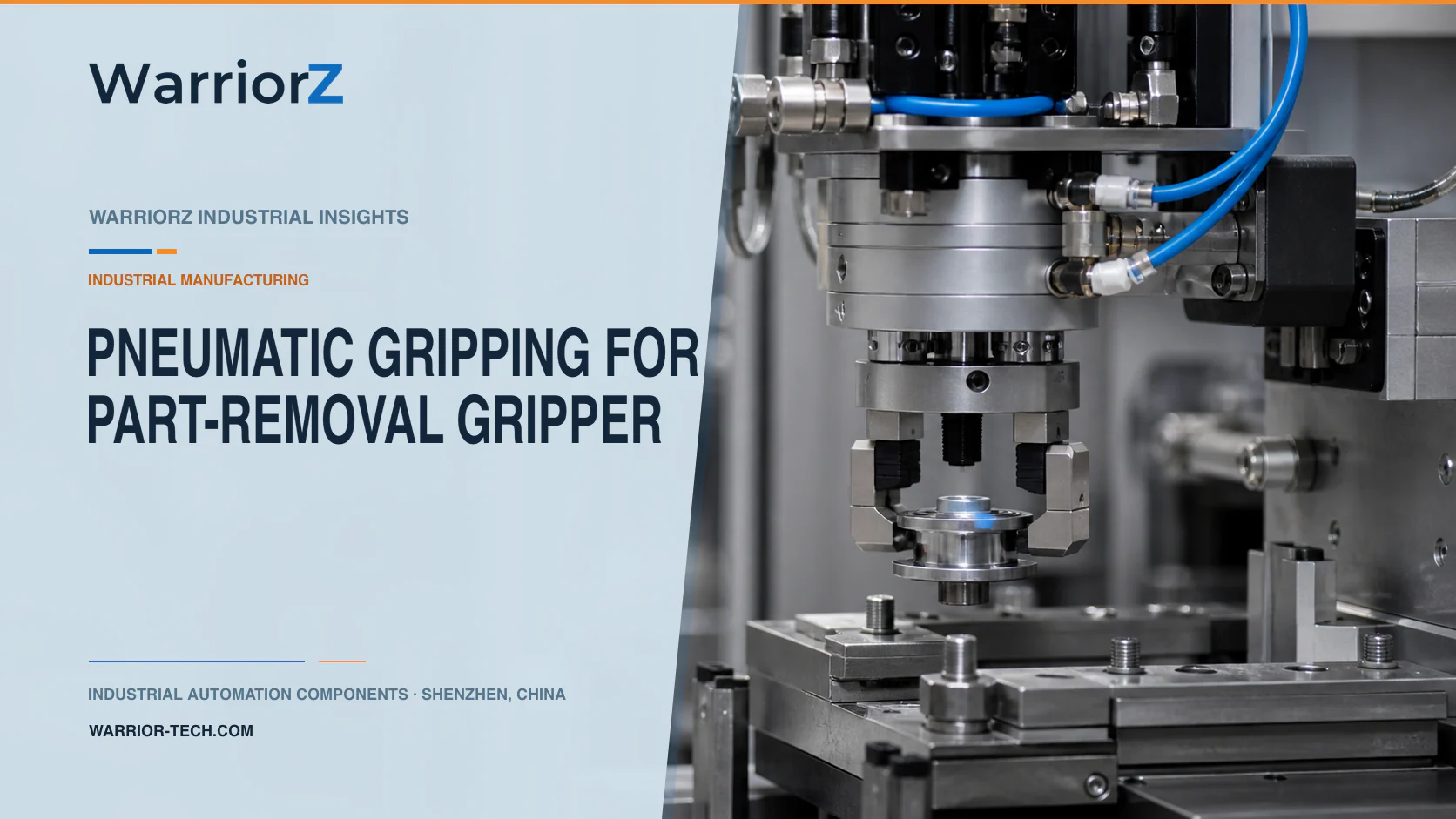
A blow molding plant often removes a hollow part while it is still warm, transfers it to a trimming fixture, holds it against a nest, and punches or cuts away neck and tail flash. Pneumatic grippers and guided cylinders can handle these motions, but the part stiffness changes rapidly after mold opening. A jaw force that works on a cool sample can deform a hot production part.
WarriorZ supplies pneumatic and industrial automation components for factory maintenance and equipment projects. The part designer and machine builder must approve grip zones, temperature windows, trimming forces, quality limits, and safety measures.
Define the part state at mold release
The application is a blow-molded container or technical-parts factory. After the mold opens, a takeout device grips the part, transfers it to a flash-trimming station, locates it in a nest, and holds it while a guided punch or cutter removes excess material.
Create a part-state matrix for resin, mass, wall distribution, mold temperature, cooling time, surface temperature at pickup, neck and tail geometry, flash thickness, and allowed deformation. Measure at the actual grip time. A fixed delay does not guarantee a fixed part temperature when cycle conditions or cooling performance change.
Part or process input | Risk during handling or trimming | Evidence to collect |
|---|---|---|
High release temperature | Permanent jaw dent or ovality | Temperature and conditioned dimensions |
Thin or uneven wall | Local collapse under gripping | Section-specific contact-force trials |
Variable flash thickness | Changing punch reaction or incomplete trim | Cut result and tool-force behavior |
Mold-release residue | Lower grip friction and pad contamination | Slip and cleaning inspection |
Part shrinkage | Changing datum and jaw position | Position window over the cooling interval |
Trapped internal pressure | Part movement or unsafe opening | Approved venting and process-state check |
Grip strong geometry with broad, qualified contact
Contact a structural region identified by the part designer, such as a reinforced neck feature or supported body zone. Avoid thin decorative panels, functional sealing faces, labels, threads, and areas that remain unsupported. Shape the fingers to spread load and prevent edge contact.
Festo's official HGPP parallel-gripper technical data provides product-specific force, stroke, load, sensing, and operating information. Any chosen gripper must be checked with the custom fingers, offset, temperature at the gripper location, duty cycle, supply range, and external moments.
Regulated pressure helps limit grip force but does not prove that the hot part is retained without damage. Finger geometry, friction, pad compression, linkage, and material condition matter. Establish a qualified window using hot production-equivalent parts. Check dimensions and surface condition after the part reaches the product's defined conditioning state.
Support the part before applying trimming force
Transfer the part into a nest that supports the trimming reaction close to the cut. The gripper should locate or stabilize the part as approved, not absorb the entire punch force through a soft wall. Use hard datums on robust features and compliant support only where tolerance analysis permits it.
The trimming cylinder requires a guide or press structure sized for cutting force, tool offset, and side load. Keep the die aligned and provide a path for severed flash. Do not increase cylinder pressure to overcome a dull tool, misalignment, or jam. That can deform the part, overload the mechanism, or eject material.
Verify the actual part and tool state before each trim. A cylinder end switch can be reached when the part is missing or the flash folds instead of cutting. Combine tool travel or force behavior with a result check appropriate to the defect risk.
Sequence takeout, nesting, trimming, and release
The mold and takeout device must exchange clear permissions. Gripping begins only when mold motion is in the defined state and the part is accessible. The part remains controlled during transfer. Trimming starts only after the nest, hold-downs, and tool path are valid.
Sequence state | Required confirmation | Fault response |
|---|---|---|
Mold ready for takeout | Machine state and access permission valid | Keep gripper outside the mold zone |
Part gripped | Jaw travel and approved grip evidence accepted | Do not withdraw the part |
Mold clear | Takeout path and part position valid | Inhibit mold closing |
Part nested | Datums and supports reached | Keep trimming tool retracted |
Hold-down engaged | Qualified clamp position and pressure behavior | No punch or cutter motion |
Trim completed | Tool result and flash path accepted | Preserve part identity for review |
Tool and clamps clear | Full withdrawal confirmed | Allow unloading and next cycle |
Avoid automatic retries after incomplete trimming. A partly cut flash can fold into the die or hold the part in an unexpected position. Stop, preserve the cycle state, and use an authorized recovery procedure.
Manage heat, contamination, and scrap
Keep gripper seals, sensors, tubes, and cables away from radiant heat and direct contact with the part where practical. Measure temperature at the proposed component mounting location during representative production. Check current manufacturer limits for the exact component and sensor.
Pads can collect resin, release agent, dust, or sharp flash fragments. Define inspection and replacement limits. A fragment embedded in a soft pad can mark every following part. Route pneumatic exhaust so it does not blow trimming scrap back into the die or onto a hot surface.
Design the scrap chute for the actual flash shape. Light, stringy, or warm scrap can bridge. Detect a blocked path if the next cycle would create a jam. Compressed-air blow-off, if used, needs controlled pressure, direction, noise, and particle containment; it should not substitute for sound chute geometry.
Guard the mold and trimming hazards
OSHA's official machine guarding guidance identifies points of operation, nip points, and rotating or moving parts as hazards requiring safeguarding. The cell risk assessment must include mold closing, takeout motion, gripper pinch points, trimming tools, hot surfaces, ejected flash, and unexpected restart.
ISO 4414:2010 covers pneumatic-system safety. Select the response to air or power loss for the whole cell. A gripper may release a hot part if pressure decays, while trapped pressure can keep a trimming tool hazardous. Provide retention, support, isolation, and dissipation according to the risk assessment.
Before entering for a jam, secure the part and moving mechanisms. Exhausting a circuit is not enough if gravity, springs, mold energy, or another power source remains.
Validate hot parts and credible faults
Run all approved resins, colors, part sizes, wall distributions, release temperatures, and flash conditions. Include the hottest least-stiff part, lowest grip friction, finger and pad wear at service limits, minimum approved supply pressure, and representative tool wear.
Measure pickup success, jaw position, slip, conditioned dimensions, surface marks, trim geometry, scrap removal, and cycle time. Challenge a missing part, wrong part, folded flash, blocked chute, dull die, shifted nest, low pressure, failed sensor, stuck valve, interrupted transfer, and loss of air or power.
For another extrusion-area moisture and valve-maintenance problem, see pneumatics on plastic profile vacuum sizing tanks. To review grippers, guided actuators, valves, and sensing against approved part-state data, send a WarriorZ blow-molding inquiry.
Official sources
Sources and verification basis
These references support the documented facts, calculations, or engineering boundaries used in this article.